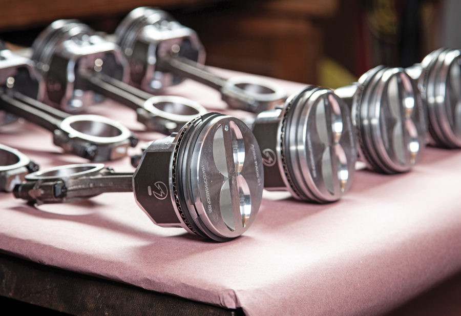
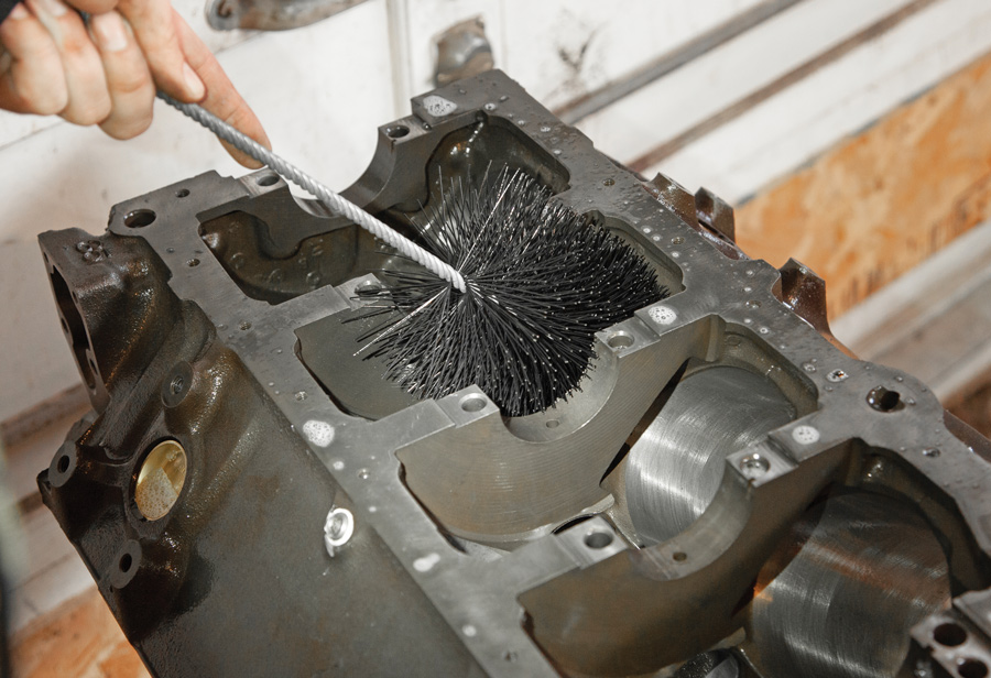
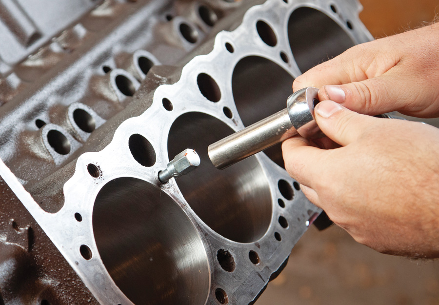
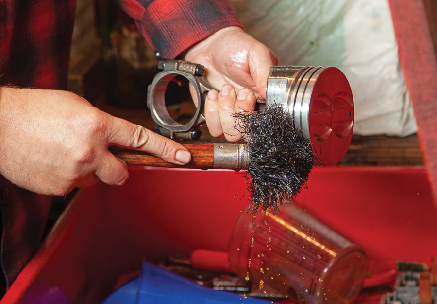
ACP department heading TECH
InTheGarageMedia.com
1. A high-mileage two-bolt main (pre 1986) small-block was sourced, disassembled, and we found it to have a stock 4.000-inch bore. We found the usual signs of wear down the cylinder walls. In general, the bones were solid but it needed a deep cleaning. After a hot bath at our local machine shop it was magnafluxed and bored 0.030 over. We also had the stock cast crank turned 0.010 under to clean up the main and rod journals. We dropped off a set of Clevite cam bearings to be installed during the visit.
Homebuilt, Old-School Small-Block Chevy
Part 1:
Bottom-End Assembly
BY Jason Lubken Photography by The Author
W

e all deserve the best bang for our buck, and that goes for anything we spend our hard-earned cash on. When it came time to decide on an engine for my own project, I asked myself the same questions you would. Why build a mild-performance engine myself if I can go aftermarket (even with a warranty) and save a ton of time? My knee-jerk reaction was to opt for the aftermarket crate options. But, as with anything, the power of peer pressure can easily justify temptation. And … I’m glad I gave in!

The real answer is, it’s all up to you. What’s your time worth? You’ll find the cost of building your own engine (reliably) from scratch isn’t much cheaper. So that leaves the big moral debate: How do you value the built-and-not-bought theme? Ultimately, I say imagine what you’ll be thinking about every time you turn the key and fire up your engine.

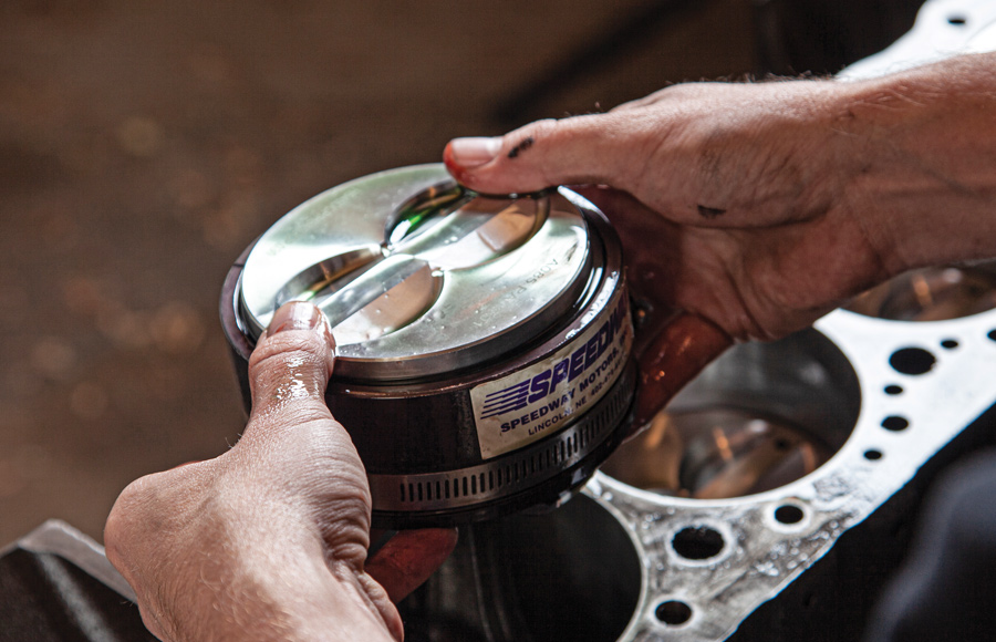
Just beware that the “built it myself” badge of honor requires more than just time. You’ll want somebody who knows what they’re doing on your side. I am fortunate enough to have some excellent resources at my fingertips. The first being a longtime friend and fellow builder, Zach Raddatz, who designed and built every inch of this SBC. I also sourced nearly all my parts list from our local speed shop, Speedway Motors in Lincoln, Nebraska.

It may be obvious, but the horsepower-per-dollar scale only goes in one direction: Up! If you want reliable power, just be prepared to pay for it. There are a ton of ways to get thrifty building a small-block, but our goal here was simple. We wanted to build a performance old-school small-block that would match the feel of a factory big-block ’63 Impala, which also happens to be my personal project. Somewhere just over 400 hp shouldn’t be hard to do with the abundance of hop-up parts the aftermarket offers. Just as important, we wanted it wrapped with an old-school look, too.

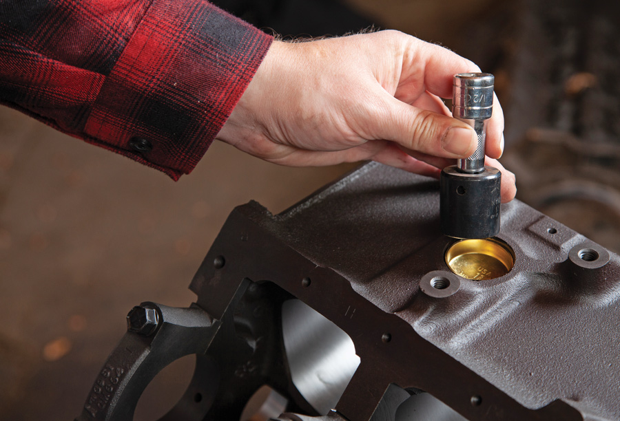
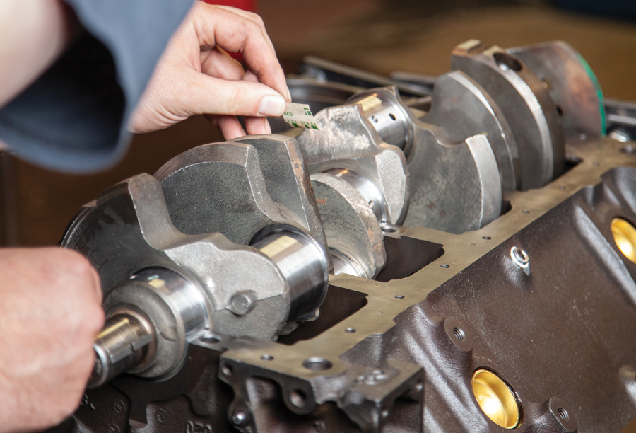
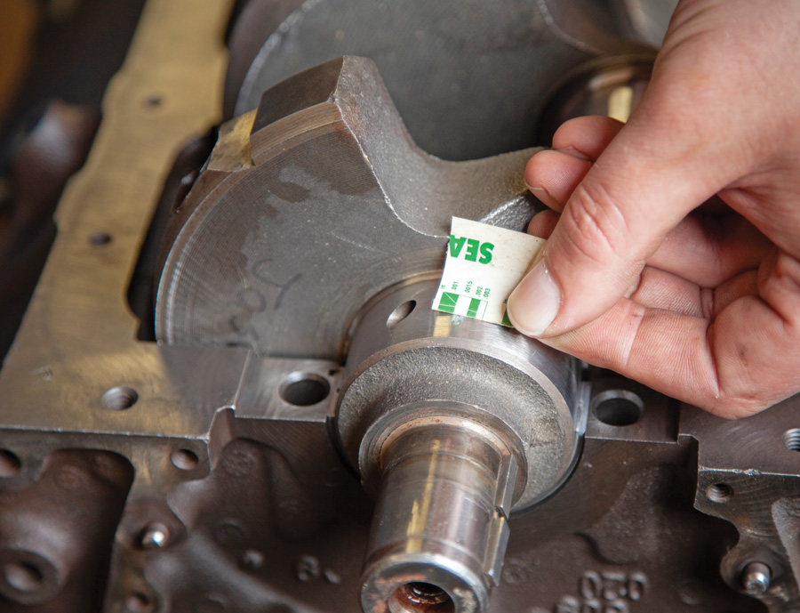
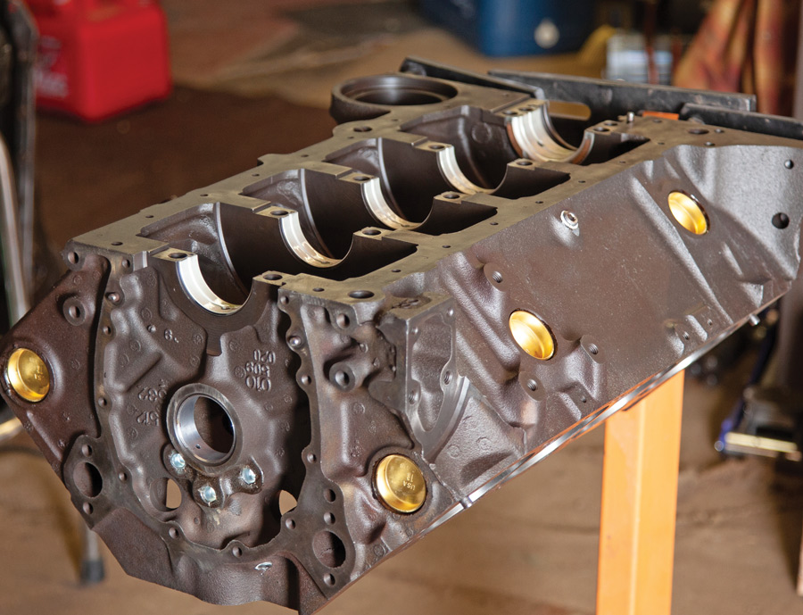
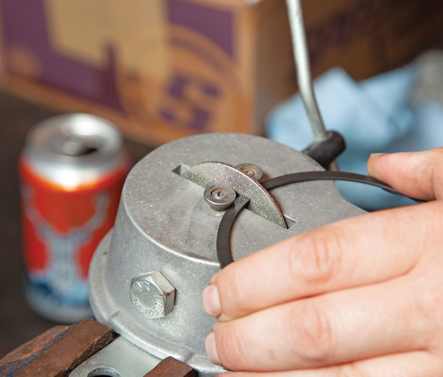
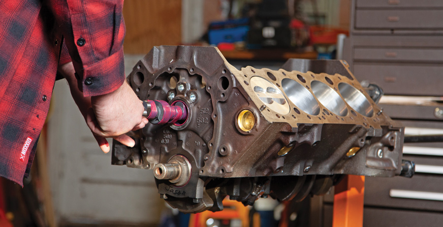
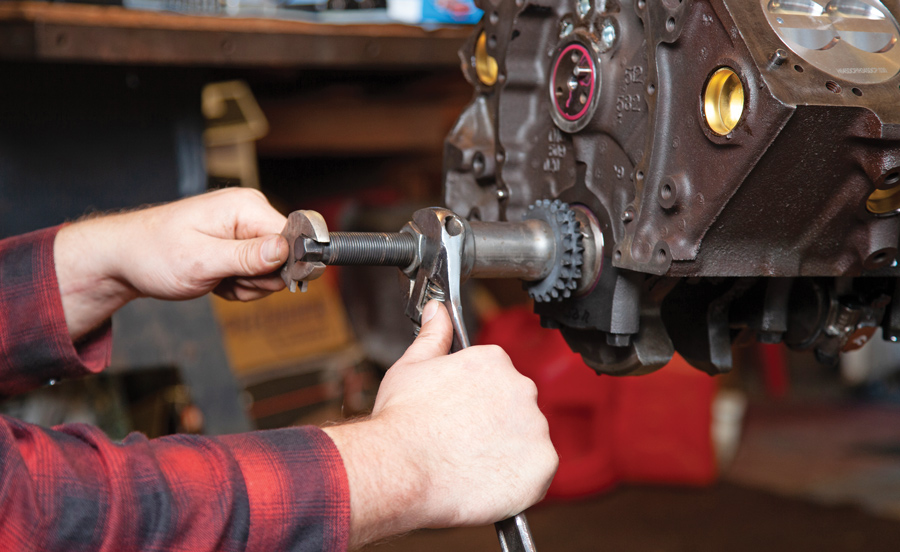
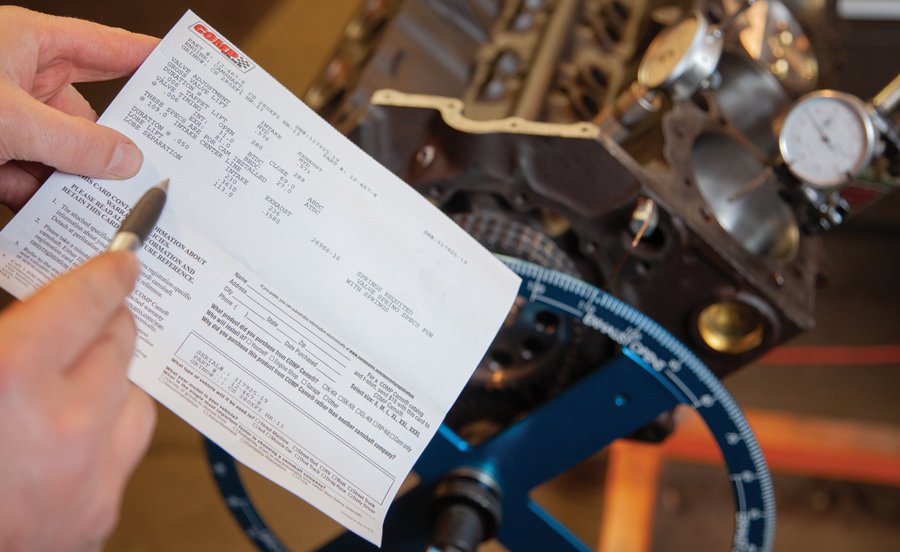
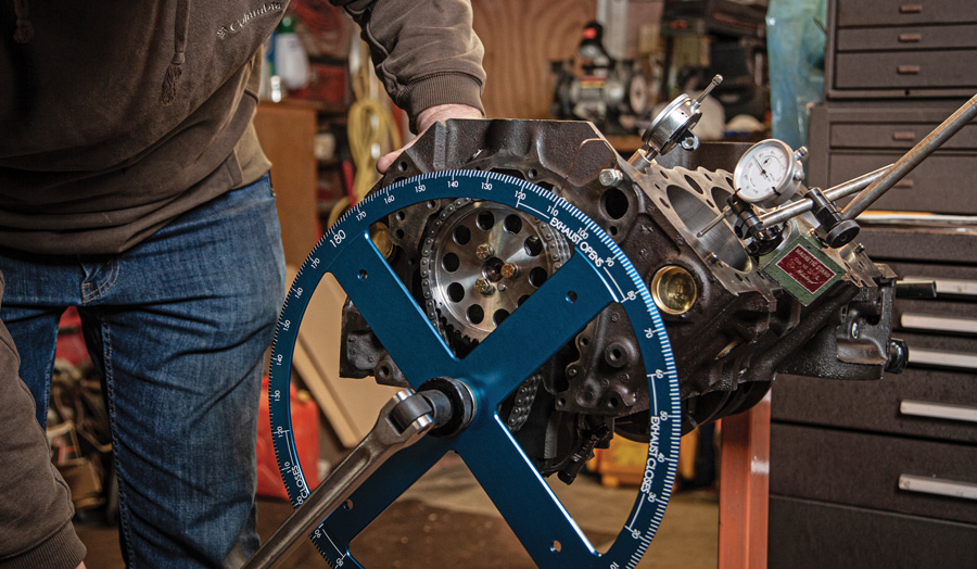
Budget-wise, my goal was to be somewhere in the middle. So, we took a used small-block 350 and had it cleaned and checked over at our local machine shop. We looked into a few upgrades too: We’ll fit it with a nicely matched Comp roller cam, and for breathability, a set of Speedway Motors aluminum double-hump heads offering 64cc combustion chambers and 2.02/1.60 valves. We’ll top it off with a Weiand Speed Warrior intake and a 750-cfm double pumper Holley Carb. After running our numbers, we should be right at our 400hp-plus mark.

Necessary Tools
Be prepared to look beyond basic hand tools if you’re building at home. Some of the must-have tools include a dial indicator deck bridge for measuring the pistons at TDC, a dial bore gauge for bearing and piston clearance, an od micrometer set, a magnet base dial indicator, plastigage, a ½-inch drive torque wrench, a piston ring filer, SAE chasing taps, and, of course, a cleaning brush kit. We found many of these tools through Speedway Motors. While you’re at it, pick up a copy of Car Tech’s How to Build a Small-Block–your bible when it comes to cross-checking torque specs, procedures, and so on.

Tune in to the next issue where we’ll button up the top-end and show you all the details on the head and valvetrain assembly.

We’ll be reusing the stock rods reconditioned with fresh 3/8-inch ARP rod bolts. We also opted for a set of 0.030-over Speed Pro hypereutectic flat-top pistons from Sealed Power.
2. We’ll be reusing the stock rods reconditioned with fresh 3/8-inch ARP rod bolts. We also opted for a set of 0.030-over Speed Pro hypereutectic flat-top pistons from Sealed Power.
Before the fun begins, the first order of business requires some elbow grease. This is a critical step after any machinework has been done. The best way to clean any leftover debris, grime, or oil left from the machining process is to clean it with a soap and water solution. We scrubbed down the block thoroughly with hot water and dawn dish soap inside and out.
3. Before the fun begins, the first order of business requires some elbow grease. This is a critical step after any machinework has been done. The best way to clean any leftover debris, grime, or oil left from the machining process is to clean it with a soap and water solution. We scrubbed down the block thoroughly with hot water and dawn dish soap inside and out.
Next, we chassed each and every threaded hole with the properly sized thread chaser.
4. Next, we chassed each and every threaded hole with the properly sized thread chaser.
Prior to assembly, every moving component was scrubbed down in a solvent tank, rinsed with brake clean, and blown dry with compressed air. Rinse and repeat when/if necessary.
5. Prior to assembly, every moving component was scrubbed down in a solvent tank, rinsed with brake clean, and blown dry with compressed air. Rinse and repeat when/if necessary.
We drove in a new set of brass freeze plugs with a slightly undersized socket and extension. We also applied a thin layer of sealer around each plug prior to installation.
6. We drove in a new set of brass freeze plugs with a slightly undersized socket and extension. We also applied a thin layer of sealer around each plug prior to installation.
Before moving onto our piston and ring measurements, we thoroughly cleaned and dried the crankshaft before we dry-installed it into the block. Prep your green plastigage and prepare to install the main caps with the bearings in place. Be sure not to rotate the crank during this procedure as the bearing contact surfaces are dry.
7. Before moving onto our piston and ring measurements, we thoroughly cleaned and dried the crankshaft before we dry-installed it into the block. Prep your green plastigage and prepare to install the main caps with the bearings in place. Be sure not to rotate the crank during this procedure as the bearing contact surfaces are dry.
Using about ¼-inch length of plastigage placed on the crank journals, torque down your main/rod caps and then remove them. In general, the bearing clearance spec should be 0.001 inch for every inch of journal diameter. You can also re-check by measuring the main and rod journals with a micrometer and subtracting the numbers from measurements taken with a dial bore gauge on the installed bearings. For example, a factory target spec might be 0.0024 inch on the mains and 0.0021 inch on the rods.
8. Using about ¼-inch length of plastigage placed on the crank journals, torque down your main/rod caps and then remove them. In general, the bearing clearance spec should be 0.001 inch for every inch of journal diameter. You can also re-check by measuring the main and rod journals with a micrometer and subtracting the numbers from measurements taken with a dial bore gauge on the installed bearings. For example, a factory target spec might be 0.0024 inch on the mains and 0.0021 inch on the rods.
After bearing clearance is checked on the crank and before final install, apply assembly lube to each of the main bearing surfaces and install the crank following the proper torque procedure on the main caps. We installed a set of Clevite 0.010-under bearings (Speedway PN 757M338-010). Prior to install we also checked that we were within spec for crankshaft endplay.
9. After bearing clearance is checked on the crank and before final install, apply assembly lube to each of the main bearing surfaces and install the crank following the proper torque procedure on the main caps. We installed a set of Clevite 0.010-under bearings (Speedway PN 757M338-010). Prior to install we also checked that we were within spec for crankshaft endplay.
After cleaning, we checked our piston-to-cylinder wall clearance to ensure proper spec. We chose to subtract the cylinder bore size from the piston diameter. Our Sealed Power Pistons have a window marked on the piston skirt indicating where to obtain the measurement. You can also reference your Sealed Power box for recommended clearance specs.
10. After cleaning, we checked our piston-to-cylinder wall clearance to ensure proper spec. We chose to subtract the cylinder bore size from the piston diameter. Our Sealed Power Pistons have a window marked on the piston skirt indicating where to obtain the measurement. You can also reference your Sealed Power box for recommended clearance specs.
Here you’ll want to ensure each piston has the proper clearance between the cylinder walls and piston skirts. Record each measurement before moving on to check the bore size.
11. Here you’ll want to ensure each piston has the proper clearance between the cylinder walls and piston skirts. Record each measurement before moving on to check the bore size.
We used a dial bore gauge to check each cylinder bore size with the corresponding piston. We took our measurement in three places: top, middle, and bottom.
12. We used a dial bore gauge to check each cylinder bore size with the corresponding piston. We took our measurement in three places: top, middle, and bottom.
We picked up a set of 0.030-over plasma moly rings (PN 9159903-030) from Speedway Motors and checked our top two ring gaps in each cylinder. You can square up the rings with a ring squaring tool or using the piston about 1 inch below the deck surface to check the initial ring gap. Use a feeler gauge to check spec—naturally aspirated engines you’re generally looking between 0.0016 and 0.0018 inch
13. We picked up a set of 0.030-over plasma moly rings (PN 9159903-030) from Speedway Motors and checked our top two ring gaps in each cylinder. You can square up the rings with a ring squaring tool or using the piston about 1 inch below the deck surface to check the initial ring gap. Use a feeler gauge to check spec—naturally aspirated engines you’re generally looking between 0.0016 and 0.0018 inch.
Our measurements came close but needed some fine-tuning. We used a piston ring filer to dial each ring gap to our desired specs.
14. Our measurements came close but needed some fine-tuning. We used a piston ring filer to dial each ring gap to our desired specs.
Before installing each piston, we let them soak in a bath of oil prior to installation. We used an adjustable piston ring compressor and gently guided each piston down with a rubber handled mallet. Near the crankshaft, be sure to route each rod into place gently to prevent any damage to the crank journals.
15. Before installing each piston, we let them soak in a bath of oil prior to installation. We used an adjustable piston ring compressor and gently guided each piston down with a rubber handled mallet. Near the crankshaft, be sure to route each rod into place gently to prevent any damage to the crank journals.
Note the dot marking each piston ensuring they are forward-facing in the block. The rod caps were installed and torqued to 50 lb-ft.
16. Note the dot marking each piston ensuring they are forward-facing in the block. The rod caps were installed and torqued to 50 lb-ft.
With the rotating assembly installed, we moved onto the cam and timing gearset. Raddatz specked out a Comp Cams hydraulic roller cam grind (PN CS 280XFI), part of Compo’s top-end kit (PN CCA-K12-432-8). This cam is designed to be perfectly streetable with plenty of chop to the exhaust note.
17. With the rotating assembly installed, we moved onto the cam and timing gearset. Raddatz specked out a Comp Cams hydraulic roller cam grind (PN CS 280XFI), part of Compo’s top-end kit (PN CCA-K12-432-8). This cam is designed to be perfectly streetable with plenty of chop to the exhaust note.
Apply a generous amount of assembly lube to each of the cam journals prior to installing the camshaft. You can also look into using a camshaft installation tool to ease the process here, too.
18. Apply a generous amount of assembly lube to each of the cam journals prior to installing the camshaft. You can also look into using a camshaft installation tool to ease the process here, too.
Next, before installing the timing gearset, you’ll want to ensure the #1 piston is at TDC. Use a deck bridge dial indicator and rotate the engine clockwise until the piston is at its highest traveling point.
19. Next, before installing the timing gearset, you’ll want to ensure the #1 piston is at TDC. Use a deck bridge dial indicator and rotate the engine clockwise until the piston is at its highest traveling point.
With the #1 piston at top dead center, we installed a Comp Cams billet double roller timing chain set starting with the crank sprocket. We used a cam gear installation tool to install the crank sprocket with the timing dot facing up. The cam sprocket will be installed with the dot aligned to the crank sprocket.
20. With the #1 piston at top dead center, we installed a Comp Cams billet double roller timing chain set starting with the crank sprocket. We used a cam gear installation tool to install the crank sprocket with the timing dot facing up. The cam sprocket will be installed with the dot aligned to the crank sprocket.
Once we bolted on the cam sprocket with the timing chain in place, we moved onto checking our cam timing. You can consult your cam card to indicate the desired intake center line for optimum performance.
21. Once we bolted on the cam sprocket with the timing chain in place, we moved onto checking our cam timing. You can consult your cam card to indicate the desired intake center line for optimum performance.
Finally, to complete our bottom-end assembly we installed a cam degree wheel to ensure the cam timing is within Comp Cams’ desired range.
22. Finally, to complete our bottom-end assembly we installed a cam degree wheel to ensure the cam timing is within Comp Cams’ desired range.
Automotive Racing Products
(800) 826-3045
arp-bolts.com
Speedway Motors
(855) 313-9173
speedwaymotors.com