ACP Tech
InTheGarageMedia.com
By Ron Covell Images by Roadster Shop
1965 Corvette, Roadster Shop Style
Part 3: Fan Shroud and Exhaust
I

n past articles we looked at some of the preliminary work being done by Roadster Shop on this outstanding 1965 Corvette. This time, we’ll take a close look at the intricate radiator fan shroud, the all-stainless exhaust system, and the aluminum pan that seals off the bottom of the body at the rear.

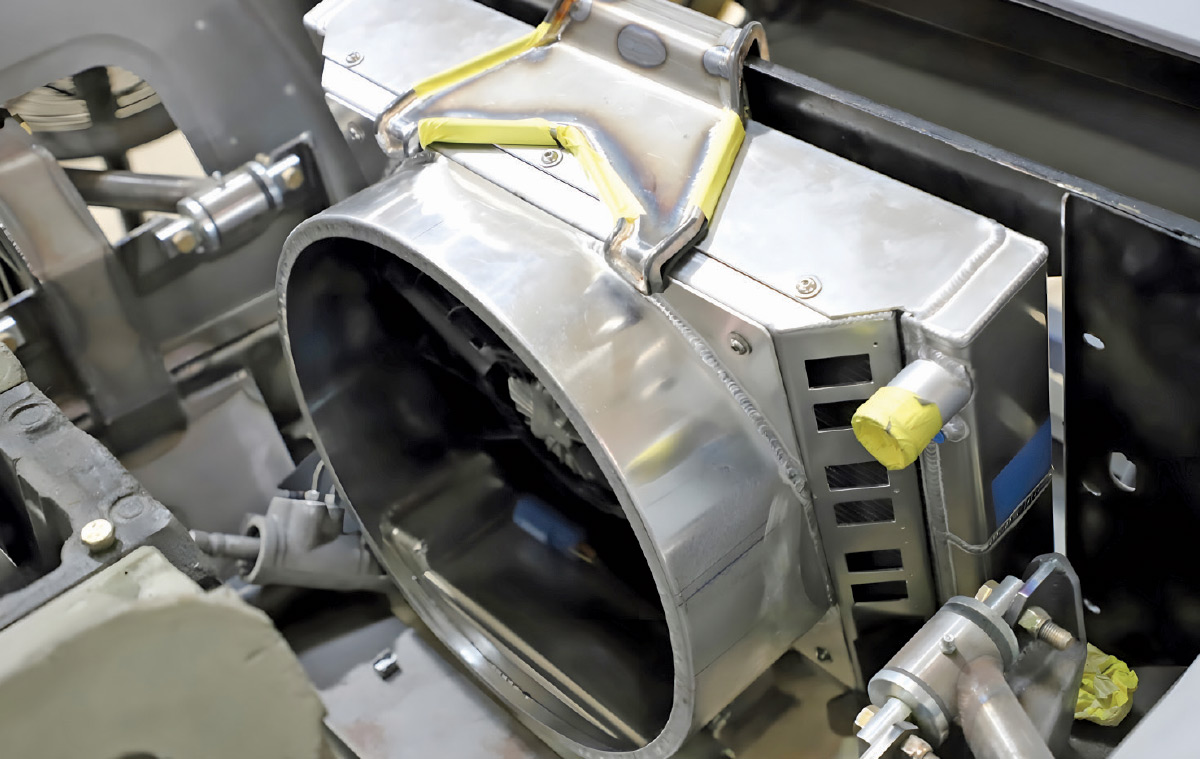
This car uses a temperature-controlled SPAL electric fan for the radiator, along with the belt-driven fan on the front of the engine. The electric fan helps manage coolant temperature, even when the car is idling for long periods and after the engine is shut off. There is precious little room under the hood of this car, so great care was taken to position each component with adequate clearance, ensuring nothing looks crowded or out of place.

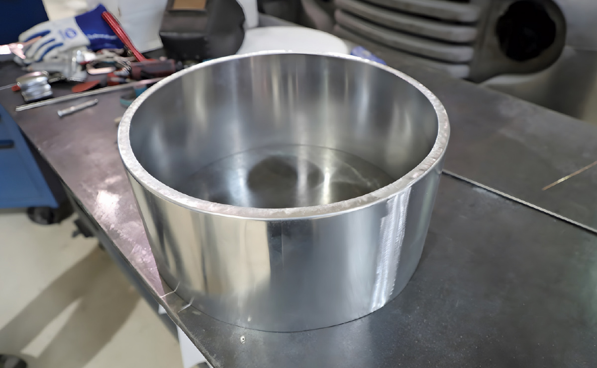
The first step was mounting the electric fan on the back side of the radiator, accomplished by making a shallow perimeter frame from sheet aluminum. Next, the circular portion of the shroud was formed by putting a 1-inch flange on a strip of aluminum and shrinking the flange to create the round shape. Once the part was accurately formed and sized, the seam was welded and metal-finished.

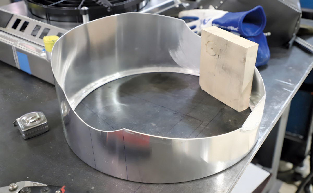
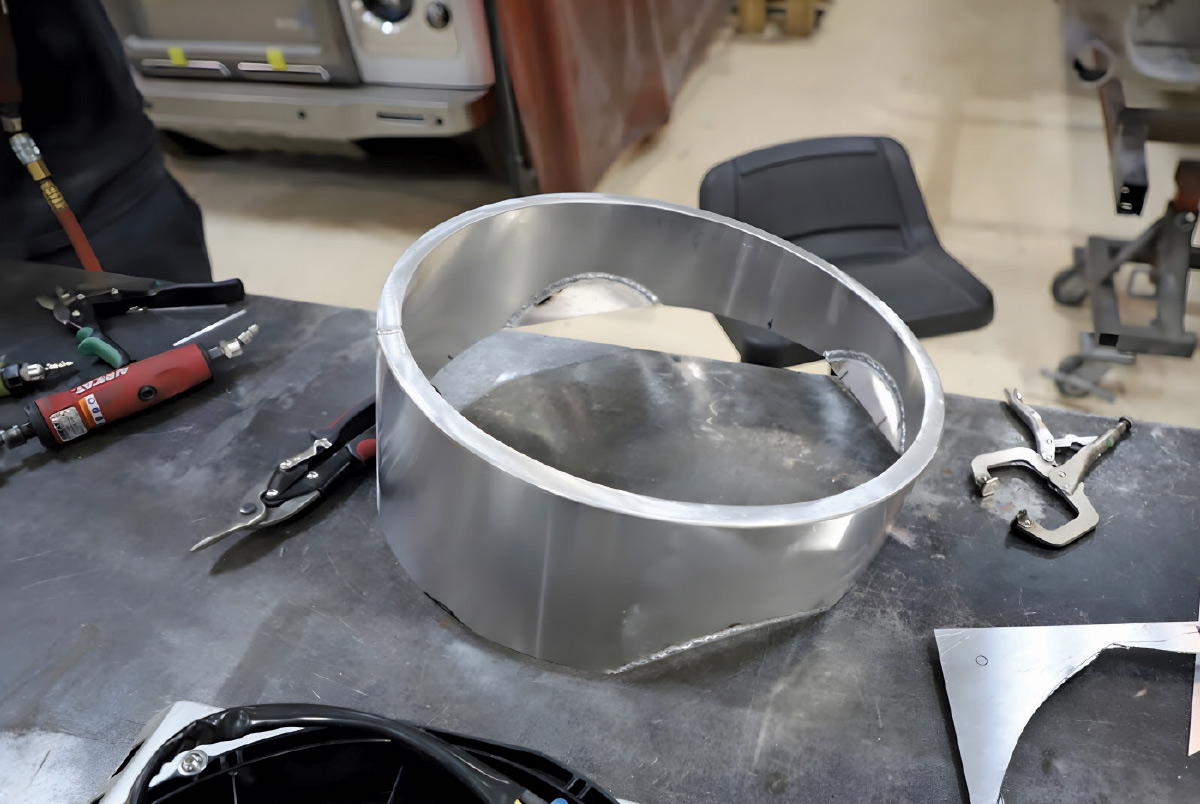
Marrying the round shroud to the rectangular frame required some creative thinking. Three sides of the circular piece were scalloped away, and the gaps were filled with flat aluminum inserts, each fitted like a puzzle piece. The bottom section was the real challenge—it needed to snake around several obstacles yet still look as though it belonged there. Through patient test-fitting and subtle shaping, the Roadster Shop team precisely developed the required geometry.

Triangular tabs were then welded to the corners of the shroud, allowing it to be mounted to the fan frame. Finally, an elegant mount was made to connect the top of the radiator to the core support.

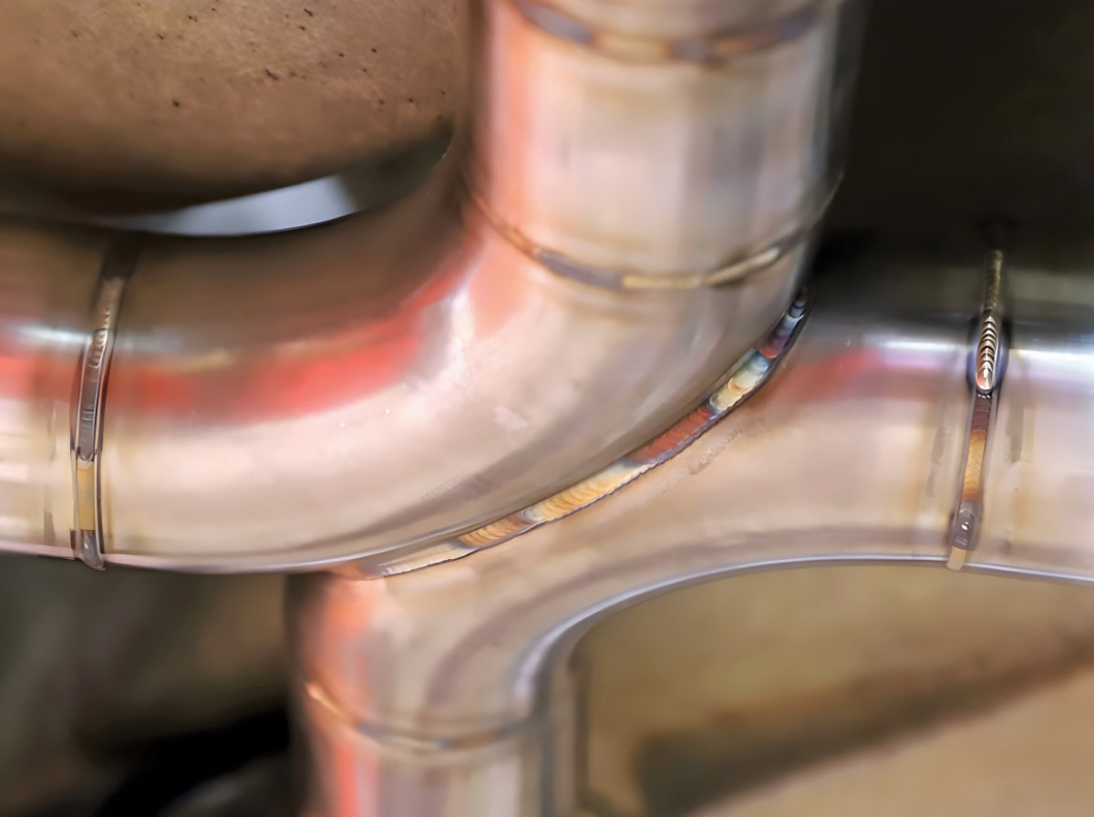
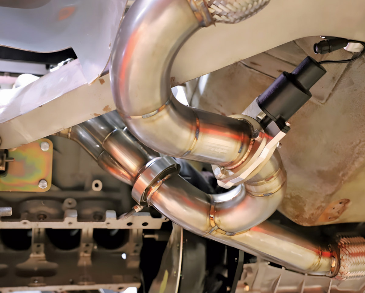
The sinuous exhaust system was built from 3-inch stainless tubing. All of the bends were painstakingly fitted to the straight sections so there are no kinks or discontinuities, keeping backpressure to a minimum. TIG welding was used throughout, and each tube was purged with argon gas to keep the inside of the weld clean and smooth.

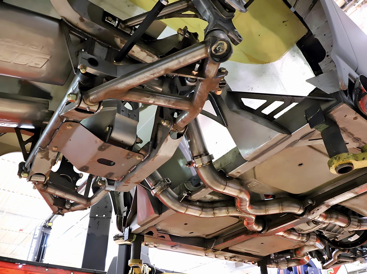
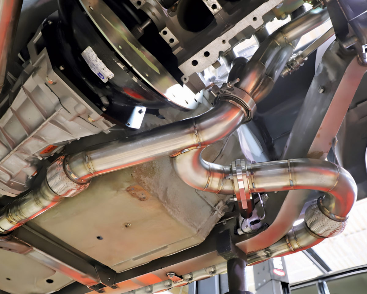
Stainless moves significantly as it heats, so several expansion joints were incorporated into the system, allowing each section to move as it “breathes.” Sturdy mounts were positioned to hold each component in place, allowing the entire system to come apart easily if service is ever required.

Electrically operated cutouts are fitted on both sides of the exhaust system, allowing the exhaust gases to bypass the mufflers at the touch of a button and be routed through the side pipes.

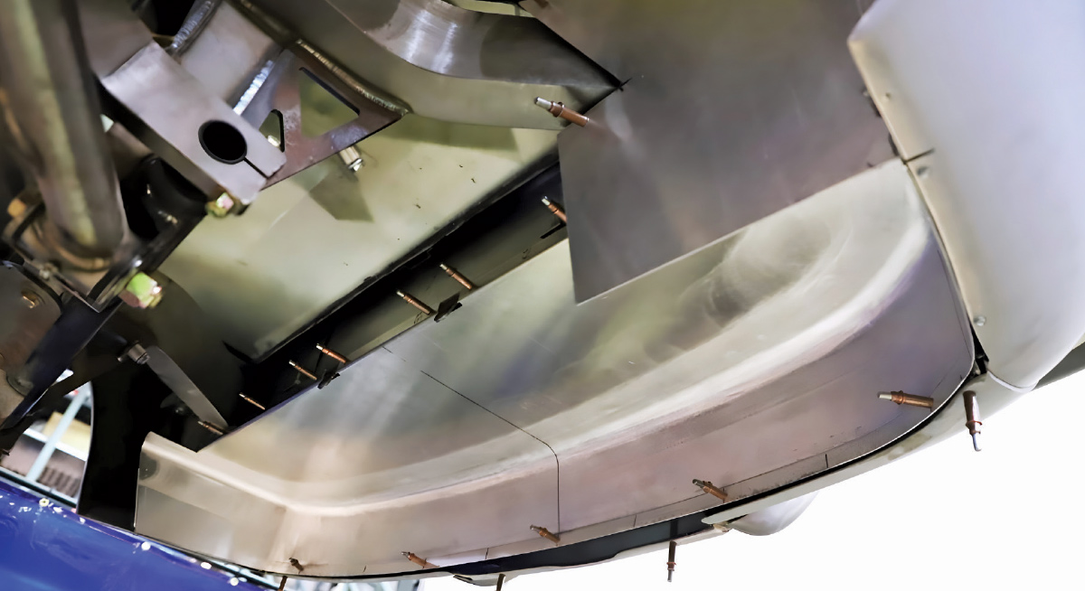
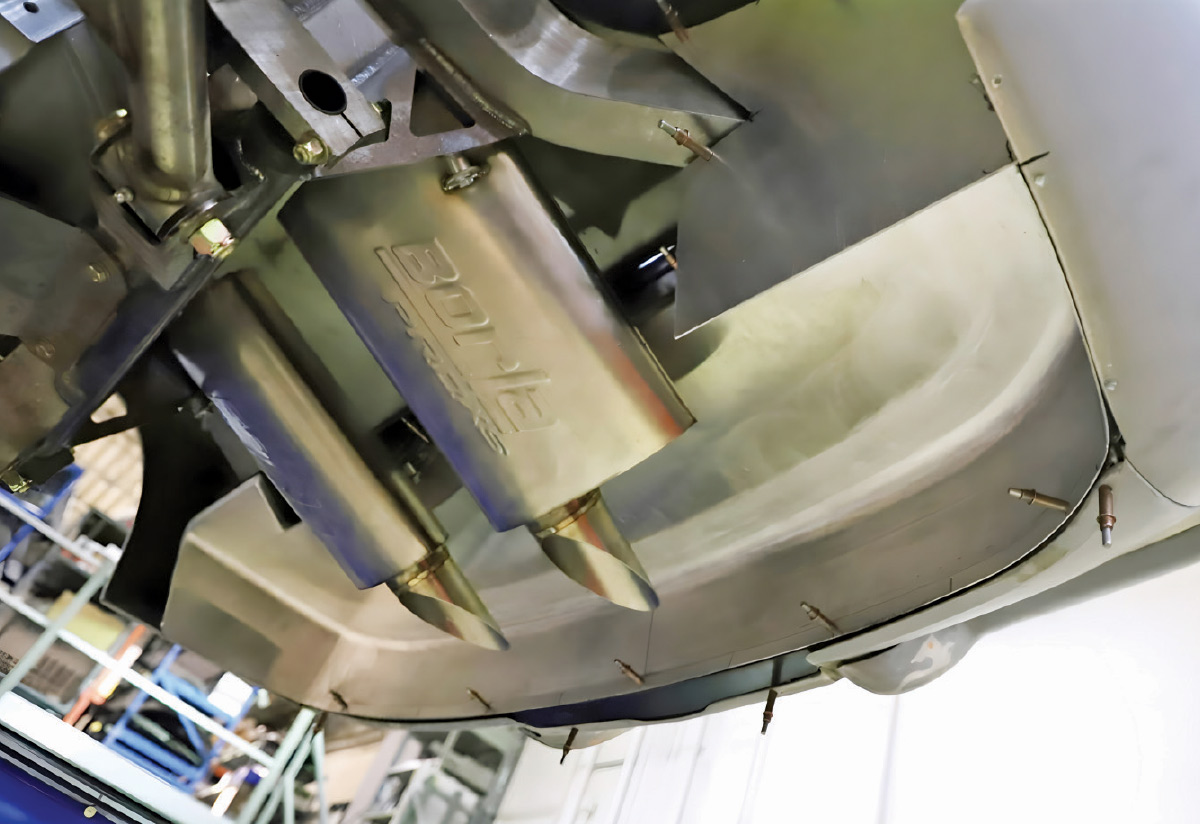
The mufflers are concealed behind the rear suspension, and the original openings in the body for the exhaust tips were filled in for a cleaner look. Short, nearly invisible tips now direct the exhaust downward; you won’t see them unless you’re willing to crouch down and look carefully.

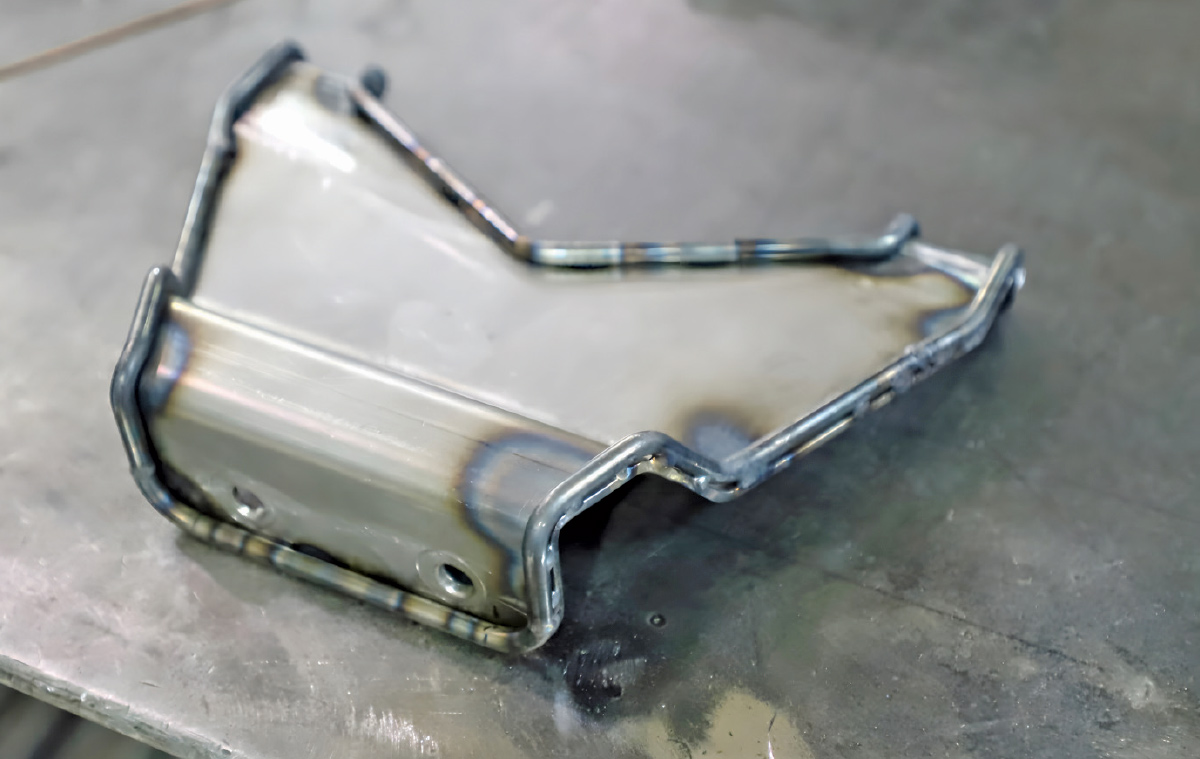
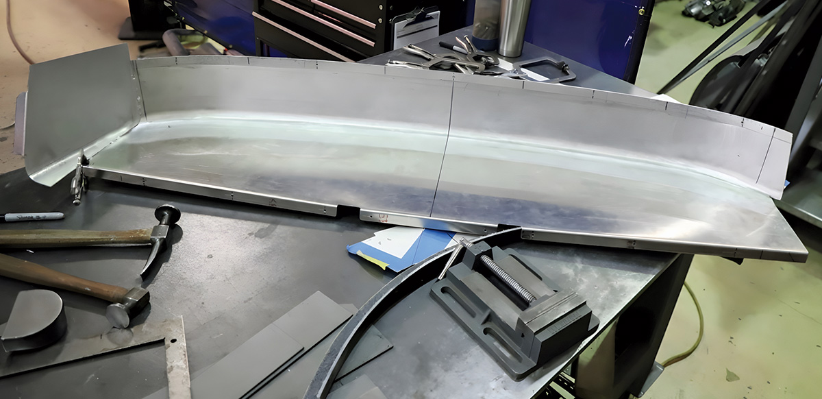
The area above the mufflers was carefully enclosed with a special pan made from aluminum sheet, which finishes off the underside of the body in an elegant manner.

In a future issue, we’ll explore how the final details came together on this beautifully constructed car, and how each finishing touch adds another chapter to its transformation.

A square aluminum fan shroud component with a large center circular cutout on a workbench.
1. A mount was fabricated from aluminum sheet to hold the SPAL electric fan and the shroud for the engine-driven fan.
An aluminum radiator and electric cooling fan assembly mounted inside a car chassis.
2. The SPAL electric fan is mounted to the radiator and checked for fit in the car.
A person uses a red industrial metal bender to shape a thin sheet of aluminum.
3. The shroud is being formed. A piece of 1/16-inch aluminum sheet was bent on a brake to form a 1-inch flange, and the shroud is curled by shrinking this flange.
A completed circular aluminum ring component sitting on a dark metal workbench.
4. Once the final contour is achieved, the seam on the shroud is TIG welded.
A curved aluminum sheet being fitted on a metal table next to a block of wood.
5. The front edge of the shroud is fitted to the radiator. Three sections were scalloped out, and flat stock is being fitted to match the radiator’s bottom and sides.
A welded aluminum circular shroud component resting on a workbench surrounded by tools.
6. Here, the flat sections have been added, and the welds are ready to be smoothed.
Various custom-fabricated aluminum shroud pieces and tools on a metal workbench.
7. A contoured section is added to the bottom of the shroud.
Close-up of a precisely welded aluminum fan shroud assembly.
8. The bottom of the shroud requires careful sculpting to fit snugly into place and provide the required clearance for all components.
A fabricated aluminum radiator shroud with mounting holes sitting on a workbench.
9. Mounting tabs are welded to the corners of the shroud.
Two different aluminum fan shroud components displayed together on a workshop table.
10. The shroud and fan mount are trial fitted on the bench before being installed in the car.
Close-up of a radiator assembly with fan shroud mounted, showing custom wiring and fittings.
11. The care taken while fabricating the shroud results in a perfect fit.
A small, custom-welded aluminum mounting bracket on a metal workbench.
12. A mount for the top of the radiator is made from steel sheet, with the edges reinforced using 1/4-inch round bar.
Finished aluminum radiator and fan shroud assembly mounted in the car.
13. All of the fillets around the edge bar are filled by TIG brazing, and the fit is tested.
Engine bay view showing the installed custom radiator, fan shroud, and drive belt system.
14. The fit of every component is snug, yet everything fits together perfectly and looks like it belongs.
Underside view showing a custom stainless steel exhaust system with an X-pipe.
15. The exhaust is completely custom-fabricated from stainless straight tubes and U-bends.
Extreme close-up of a precise weld on a stainless steel exhaust joint.
16. An elegant crossover is created by welding two 90-degree bends together.
Wide underside view of the chassis showing the exhaust routing and rear suspension components.
17. Moving toward the rear, the exhaust pipes curve upward to clear the Roadster Shop independent rear suspension.
Close-up underside view of the polished exhaust system and chassis frame rails.
18. Note the holes and notches in the chassis provided for the exhaust system, ensuring nothing hangs down below the car.
Detailed view of a custom exhaust hanger bracket welded to the chassis.
19. Sturdy mounts and V-band clamps allow each section of the exhaust system to be removed for maintenance.
Full underside view of the classic car on a lift, showing the entire exhaust and chassis assembly.
20. The mufflers are neatly mounted behind the rear suspension.
Front underside view of the engine and front suspension on a lift.
21. A cutout is fitted to the system, allowing the mufflers to be bypassed so the exhaust is routed through the side pipes.
Close-up underside view showing custom steering and suspension joints.
22. All of the bends in the exhaust system maintain smooth, flowing curves to minimize backpressure.
Detailed view of a custom steering rack and linkage assembly.
23. An electrically operated gate valve is used for the exhaust cutout.
Close-up of braided stainless steel fuel or brake lines and fittings under the car.
24. Flex couplings are used between each major section of the exhaust system, allowing the stainless to expand and contract without interference.
Long piece of sheet aluminum being prepared on a workbench for fabrication.
25. An aluminum rear pan is fabricated to enclose the area above the mufflers.
Aluminum panel being test-fitted under the rear of a classic car body.
26. The pan is temporarily held in place with Clecos.
View of installed Borla ProXS mufflers under the rear of the car.
27. With the mufflers mounted you can see there is plenty of clearance for all components, and the mufflers are hidden from view.
Side view of the Borla ProXS muffler assembly and exhaust tips.
28. The exhaust tips exiting the mufflers are “baloney-sliced” to keep them out of sight, and to direct the exhaust away from the bumpers and body.