ACP department heading TECH
InTheGarageMedia.com
person closely inspecting an engine
Into The Unknown
INSPECTING AN ENGINE OF QUESTIONABLE ORIGIN
By RYAN MANSON 
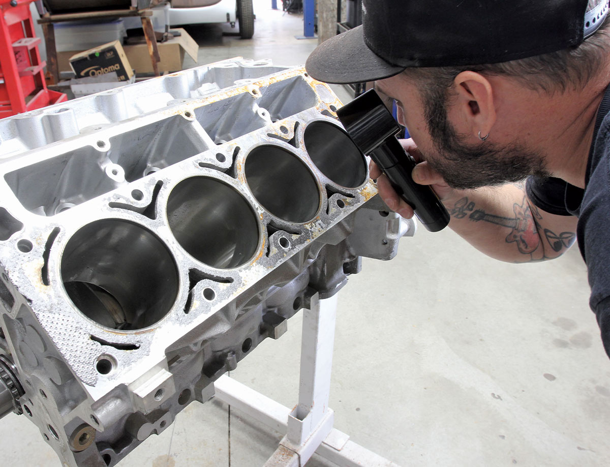
Photography by The Author
P

urchasing a used engine, be it from a friend, junkyard, or a swap meet, can be a practice in futility. Every small-block at the local high-performance swap meet has been bored and stroked, equipped with a hot cam, and originally resided in a Corvette. At least according to the seller. The truth, however, is usually much less impressive. In reality, that overbore was only applied to one cylinder, that hot cam has two flattened lobes, and the seller actually meant Chevette and not Corvette. The point is, buying a used engine is akin to buying something sight-unseen because though it might be sitting right there in front of you, what’s hiding inside usually can’t be inspected until after the deal is done. And that deal can sometimes burn.

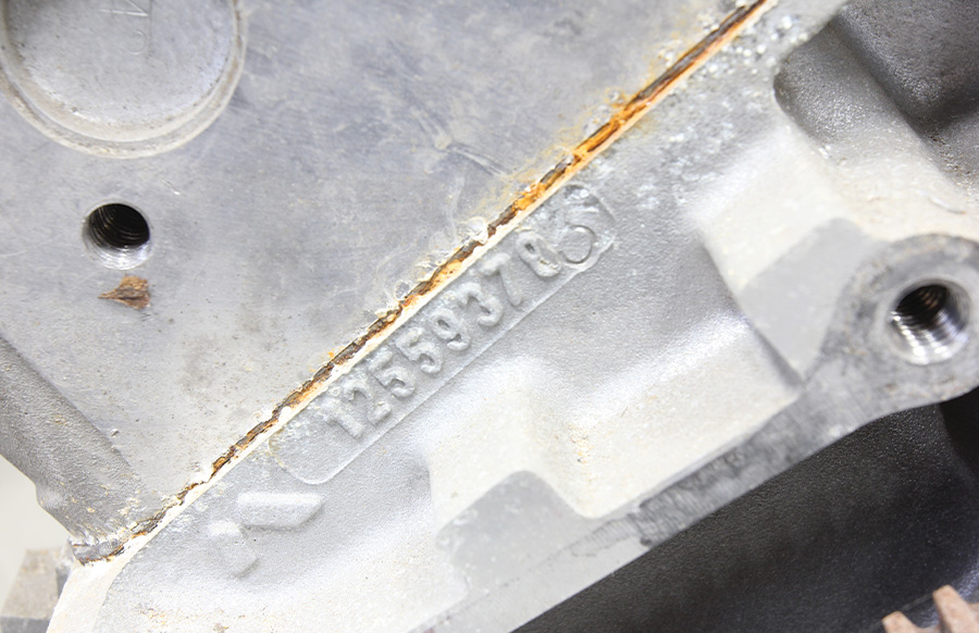
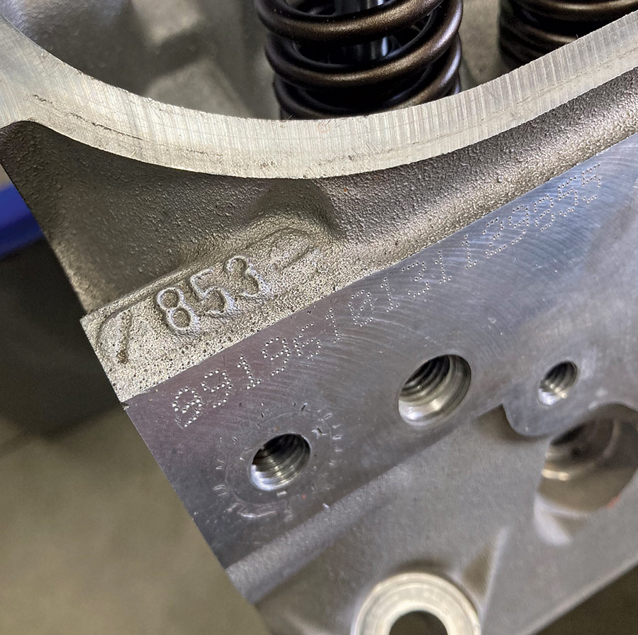
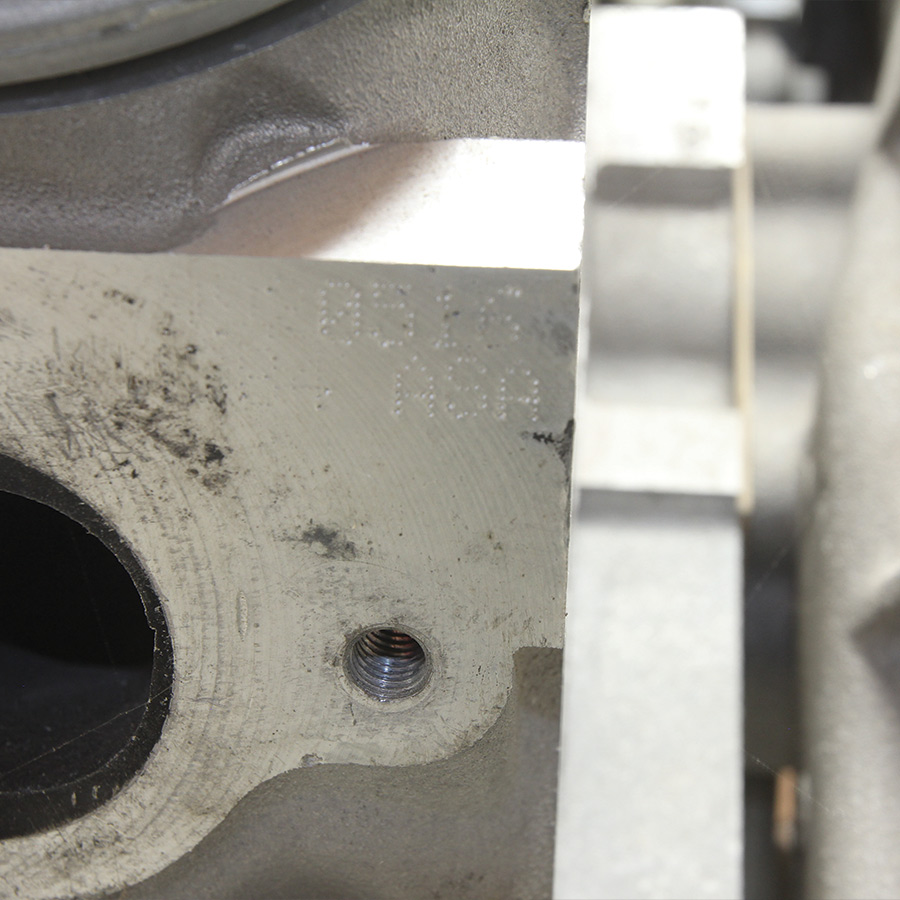
So, what can be done when it comes to buying a used engine? For starters, a heavy education in the make of engine one’s hunting for can help. Most blocks and heads can be identified by a variety of means, be it casting marks (think Camel hump heads) or casting numbers. A quick Interweb search will usually result in a fairly accurate identification that should help persuade, or dissuade, said purchase.

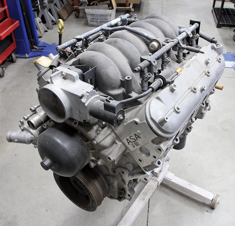
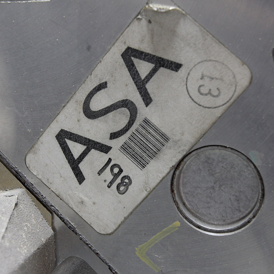
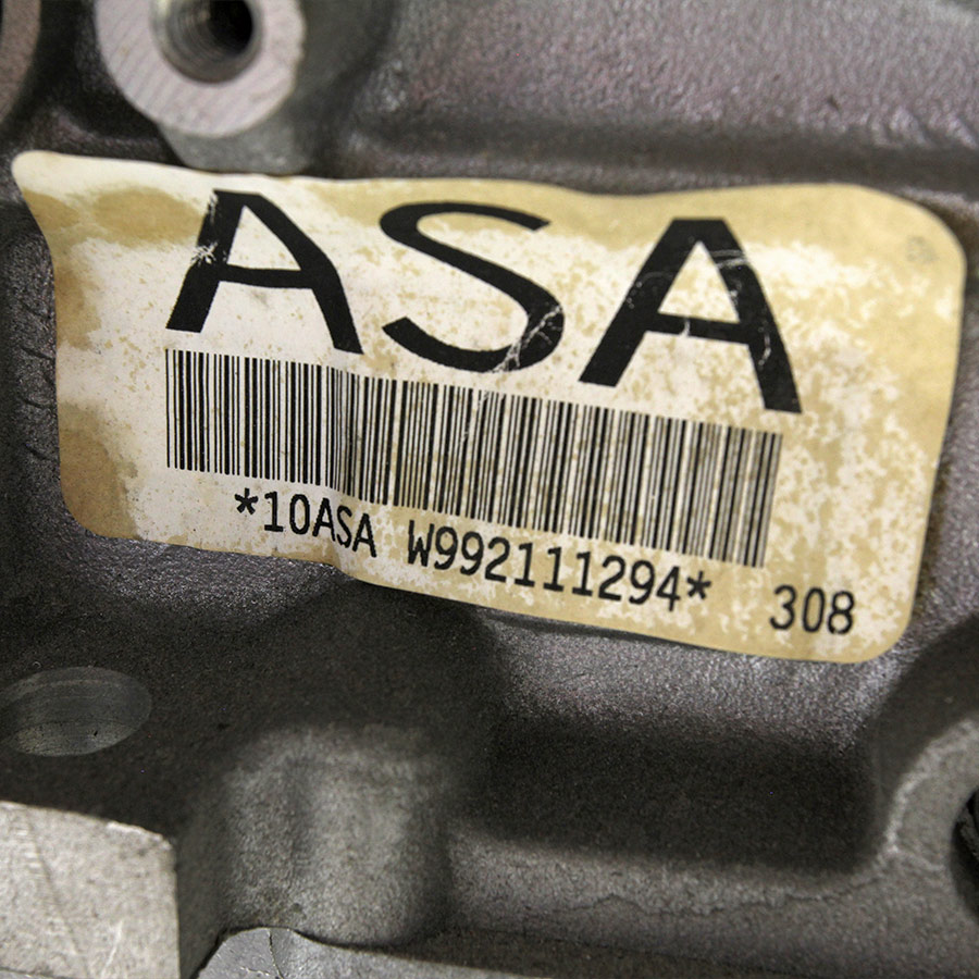
A recent discussion with our buddy Zane Cullen of Cotati Speed Shop brought up this topic spurred by the realization that the mock-up LS engine that they’ve been using in the shop for the last decade-and-a-half might actually hold some performance pedigree. After some quick sleuthing, it was determined that the early LS might have lived its younger days under the hood of a stock car. And by stock car, we mean Stock Car. Back around the turn of the century, American Speed Association (ASA) in conjunction with GM decided to regulate the engines used in the racing series and it just so happened that the guys at The General had the perfect ace in the hole in the form of their LS1 V-8. Spec’d and sealed upon delivery, every car used the same engine with the same tune to create a more perfect form of fairness.

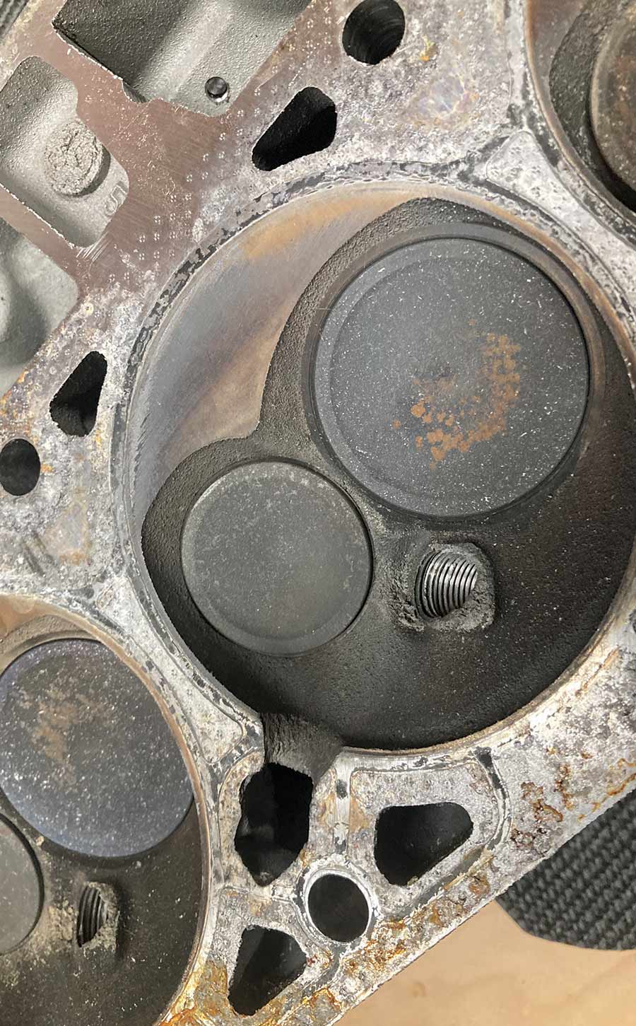
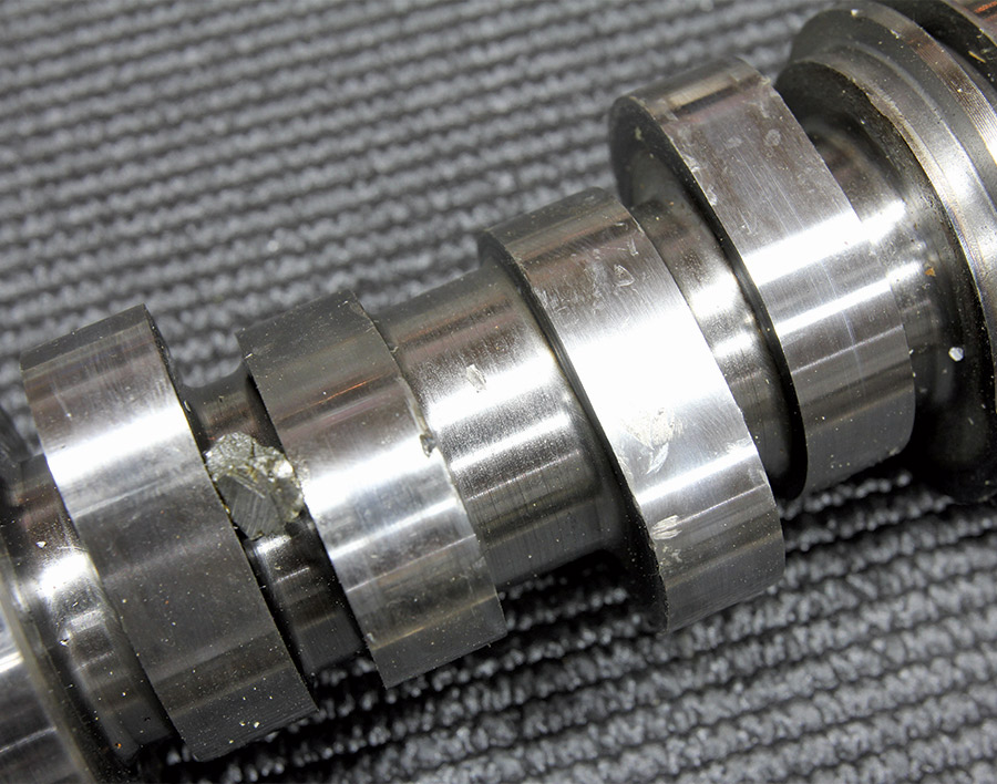
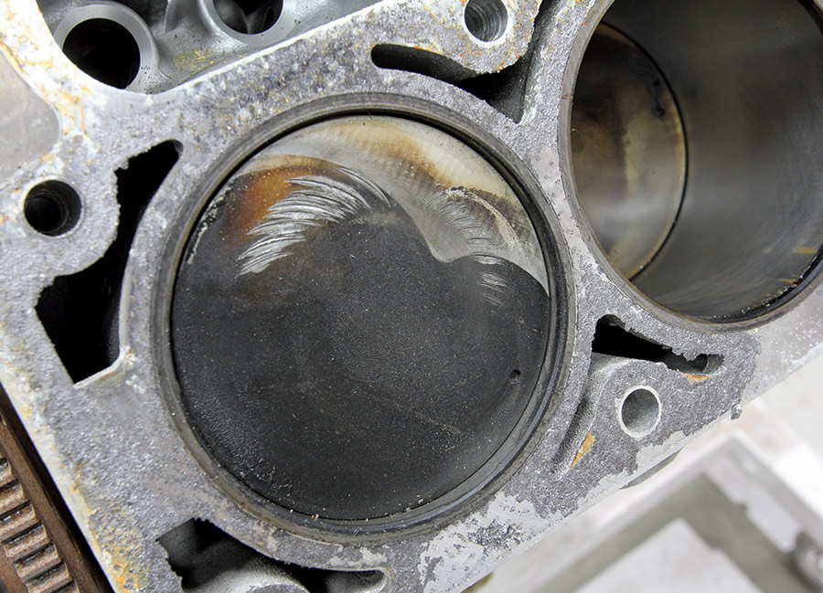
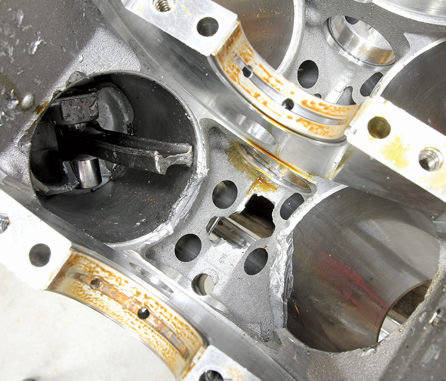
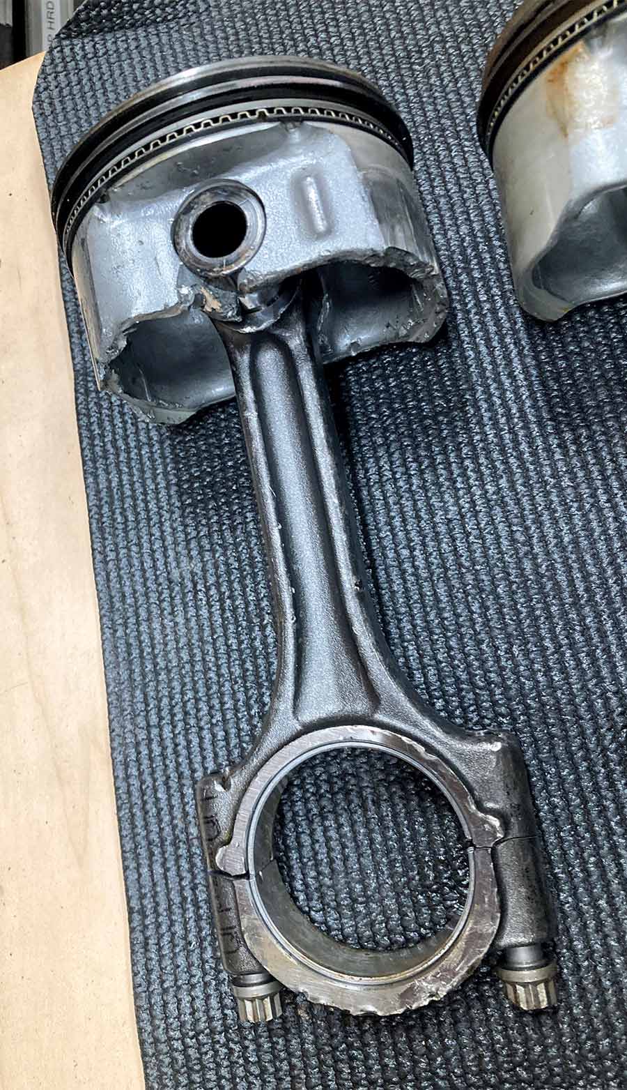
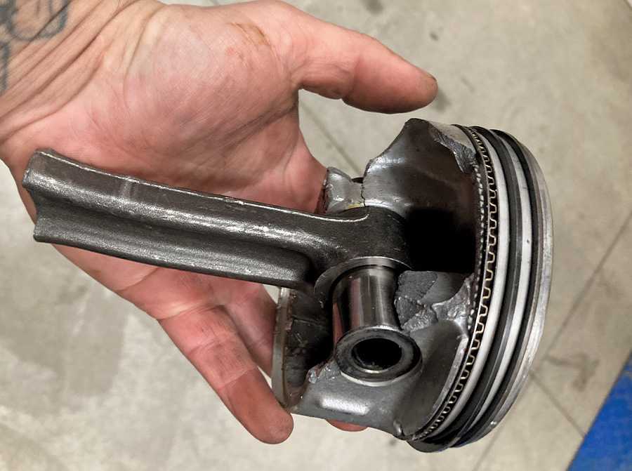
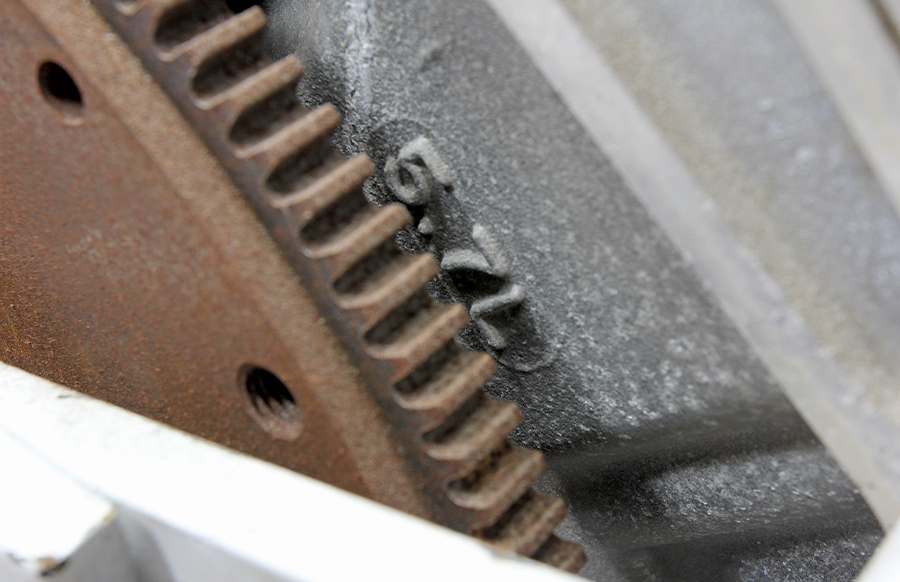
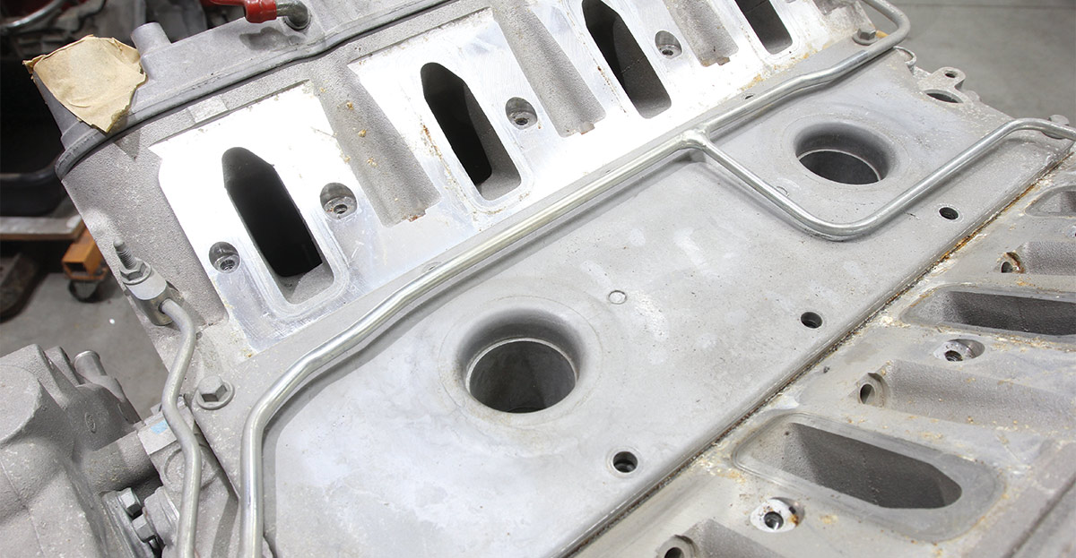
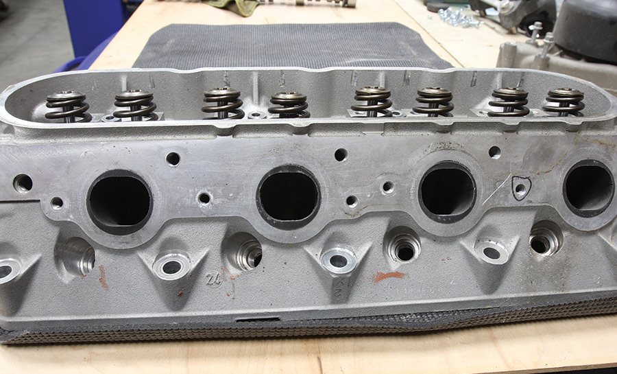
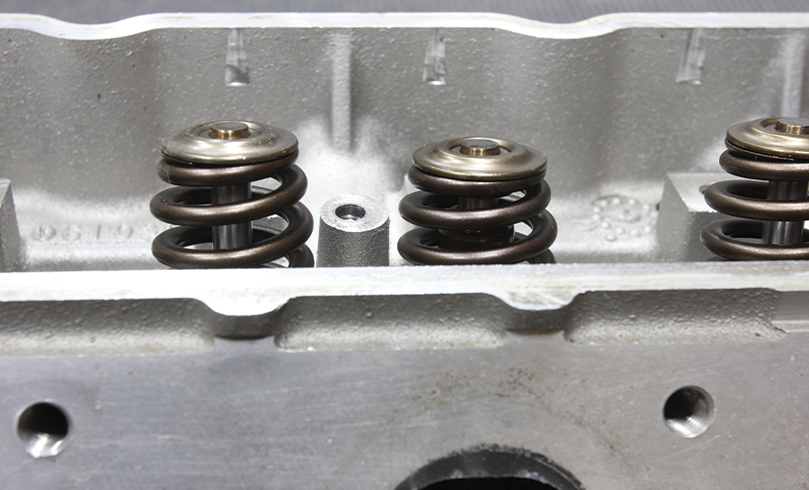
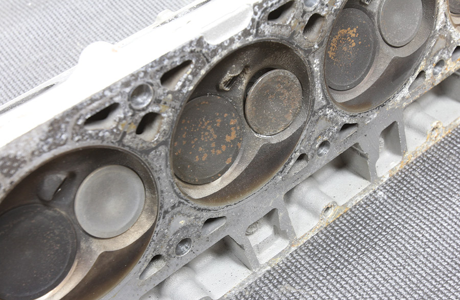
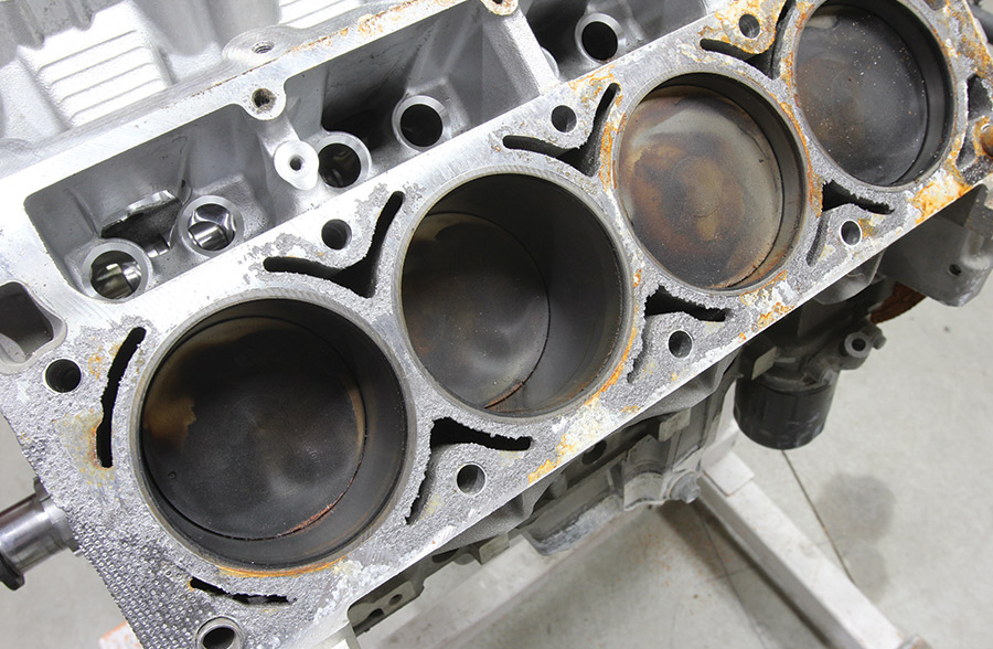
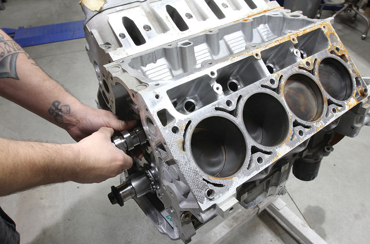
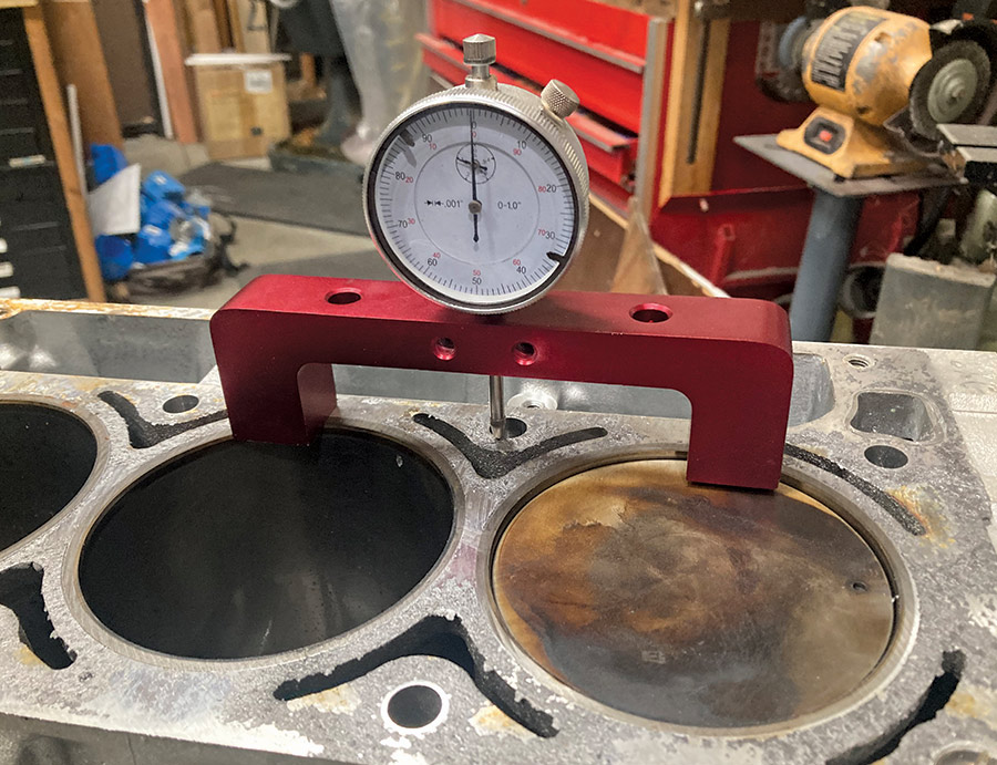
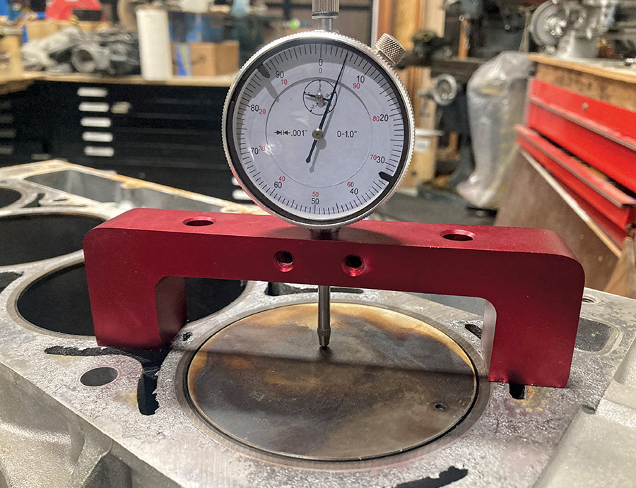
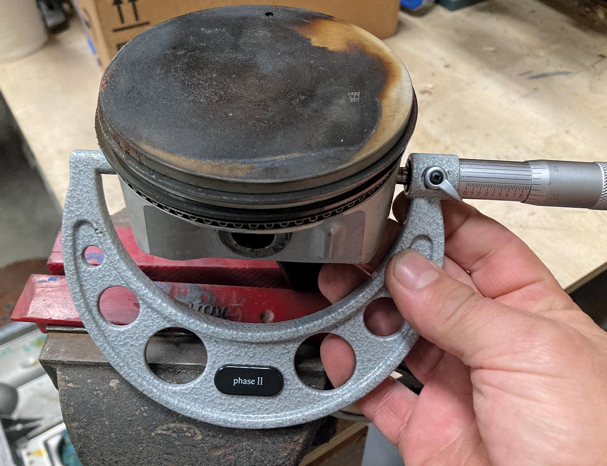
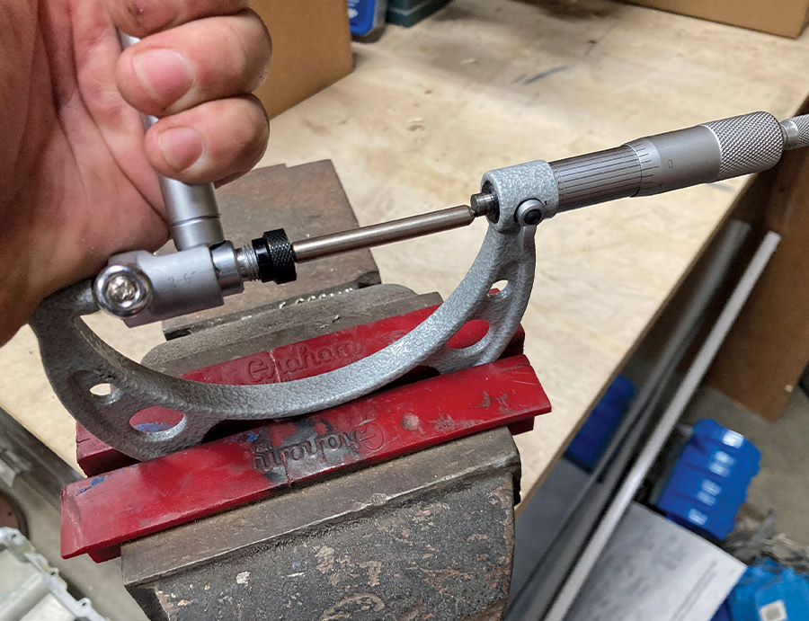
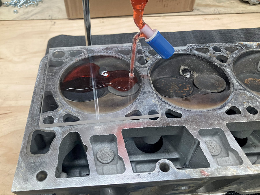
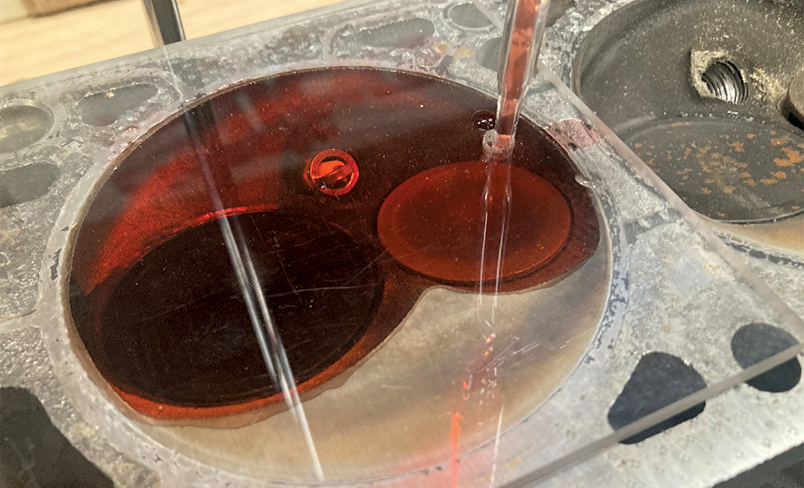
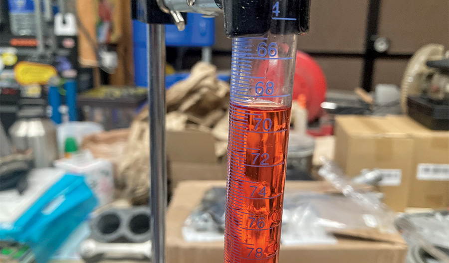
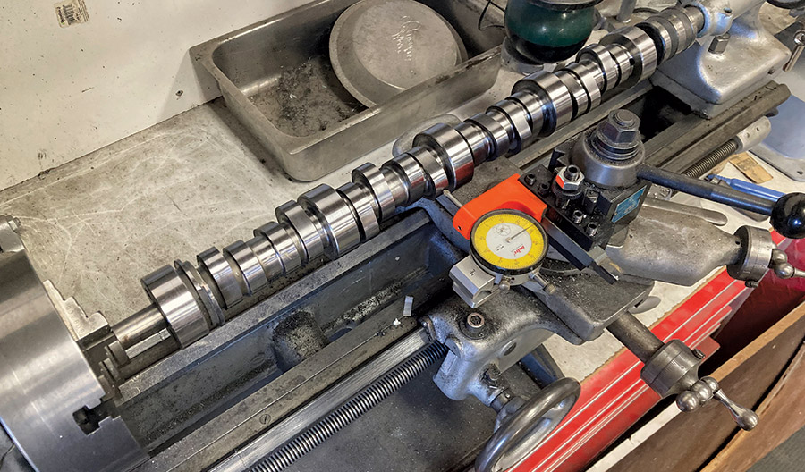
Now, all that sounds well and good, but could Cullen’s LS really be a Sierra Hotel racing engine or is it more likely to be a detuned version of the production engine, which, as it turns out, really did originate from the Corvette? He was determined to find out and dropped the powerplant off at the Clampdown Competition headquarters where it was to be opened up and inspected. What we found surprised us all, to say the least, and should serve as a lesson to all potential engine buyers that you never know what you’re gonna get!

What have we learned?
By measuring and inspecting the components on our LS engine, we’ve determined that our engine is indeed within spec of a 5.7L/346ci engine, with the original bore and stroke, camshaft profile, and compression ratio. If any of these dimensions were out of spec, it would be necessary to investigate those components further to determine if it was component-related or point to possible machine work having been made some time in the past. These details give us the information necessary to progress with our rebuild plans, what components need to be replaced, what can be reused, and whether the block and/or heads need to be machined.
car engine
1. Here’s the engine in question that’s been hanging around Cotati Speed Shop for so long. Its provenance and internal makeup is all but a mystery to Zane Cullen and the crew. We’re pretty confident that the ASA “badging” is accurate in identifying it as from the racing series, but there’s no telling whether it remains as-stock from back in the early ’00s or if it has been “modified.”
closeup of engine's casting numbers
2. One of the best methods of identifying engine components is via casting numbers. The block casting number ID’d the LS as a 5.7L/346ci engine from the ’99-00 era. That jives with the specs of the ASA LS1 engines as well as their time frame. This gives us some basic engine parameters (bore and stroke) that we’ll use to compare against our actual findings a little later.
closeup of 853 casting number on the cylinder head
3. The “853” casting number on each cylinder head yielded similar results and some more specs to use as a baseline against our engine.
closeup of a casting feature
4. Another casting feature further cements its original displacement.
ASA labeling
ASA labeling with bar code and serial number
closeup of cylinder head
5-7. ASA labeling was present on one cylinder head as well as the oil pan and etched on both heads as well, which made us feel fairly certain about what we were dealing with.
cathedral intake ports
8. After removing the intake, the cathedral intake ports on the heads and knock sensor ports in the valley cover are further indications that we’re dealing with an early LS engine.
exhaust valve
exhaust valve closeup
9-10. Inspection of the driver side cylinder head reveals a stuck exhaust valve on the number three cylinder that will need to be addressed. The valve sizing comes in at LS spec, 1.55 inch for the exhaust and 1.980 inch for the intake.
closeup of driver side cylinders
11-12. A quick look at the driver side cylinders doesn’t reveal any obvious damage. So far, so good.
person inspecting the camshaft
13. The camshaft is then removed, followed by the passenger side cylinder head and the rotating assembly to allow for a thorough inspection.
piston-to-deck height being measured
14-15. Before yanking all the pistons, piston-to-deck height is measured and noted. This will help us calculate static compression ratio. We’re right at 0.005 inch above the block’s deck. Coupled with a 0.050-inch head gasket results in 0.045-inch piston-to-head clearance.
closeup of pistons
16. First things first, we’d like to determine if the bore and stroke are true to stock or if it’s been modified. The pistons measure up with a diameter of 3.8965 inches. That dimension will be compared to the cylinder bores to determine their dimension.
dial bore gauge being used to measure the cylinder diameter
17-18. To measure the cylinder diameter, we’ll be using a dial bore gauge zero’d to the piston’s diameter as measured by a micrometer.
measurements being taken within each cylinder
19. Multiple measurements are taken within each cylinder to account for cylinder taper, wear, and so on.
dial showing the measurement of the cylinders
20. The resulting measurement tells us our cylinders are more or less 0.0015-inch larger than our pistons, giving us the piston-to-cylinder wall clearance and revealing the bore diameter to be 3.898 inch, which is stock LS spec. No overbore here! Since we’re only measuring to get a baseline on the components involved, hairs need not be split until it comes time to measure things for machining and during final assembly. For now, deviations between cylinders expected on a used engine is not something we’re concerned with at this time.
Proform Cylinder Head Kit
21. Turning our attention to the cylinder heads, we’ve set up a Proform Cylinder Head CC Kit (Summit Racing PN PRO-66831) so that we can measure the volume of the combustion chambers. This will further help us determine static compression ratio.
red-dyed water being poured into the combustion chamber
red-dyed water in the sealing plate
22-23. The combustion chamber is filled with red-dyed water until it reaches the bottom of the sealing plate.
fluid in a burette
24. The fluid remaining in the burette reveals the amount required to fill the combustion chamber, and thus its size, 68cc. Crunching the numbers via Summit Racing’s Compression Calculator results in a compression ratio of 10:1, which is very close to stock spec, telling us that the rod length is likely stock and that the deck height hasn’t been changed.
degree wheel and dial indicator determining the specs of the camshaft
25. The camshaft doesn’t feature any telltale part numbers, so determining its specs needs to be done manually. Thankfully, this isn’t all that difficult with a degree wheel and a dial indicator. A way to support and turn the cam is a must. Here, we’ve set it up in a lathe between centers, but a pair of V-blocks would work as well. The dial indicator on the cross slide will be used to determine lift by measuring the total amount from the heel of the cam (the backside, flat portion of the lobe) and the nose (the pointy part). Set to zero while on the heel of the lobe, the camshaft is slowly rotated until the dial indicator reads the highest point, giving us total lift. Spec for an ASA camshaft is 0.525 max lift with a 1.7 ratio rocker. This means that we’re looking for a dial indicator reading of around 0.309 inch (0.309×1.7).
lobe being measured
lobe being measured
26-27. Lift can also be determined by measuring the lobe across the shortest and tallest location and subtracting the smaller number from the larger.
degree wheel being used to determine the camshaft's duration
28. Determining the camshaft’s duration is a similar process, with the addition of a degree wheel. Note the indicator mount at the degree wheel is simply functioning as a pointer.
camshaft being slowly rotated until the dial indicator reads 0.050 inch
29. Since most camshaft duration companies spec it at 0.050-inch lift, we need to do the same. Starting at the heel of the cam, the camshaft is slowly rotated until the dial indicator reads 0.050 inch, giving us our first data point.
pointer on degree wheel set to 0
30. The pointer on the degree wheel is then set to 0 for easy reading.
camshaft being rotated
31. Next, the camshaft is rotated until it reaches the opposite side of the lobe from where the first 0.050-inch reading is made.
degree wheel showing 113 degrees
32. This gives us a readout of 113 degrees, which is the duration the valve is opened at least 0.050 inch. Given the camshaft turns at half speed when compared to the crankshaft, we need to double that figure, giving us a total crankshaft duration of 226 degrees for the intake side. Measuring the exhaust lobes results in 236 degrees, matching GM’s specs for their ASA camshaft that is still offered and a popular cam option for any LS engine.
SOURCES
You Win Some, You Lose Some
While the components of our LS engine checked out as they should, our lesson in inspection quickly became a lesson in depression as one thing after another started to bend the needle toward futile. By the time we had the engine completely disassembled, it was painfully obvious that our LS engine would best be re-relegated to mockup status. Thankfully, the state of this engine was alluded to by a previous owner and we’re not out anything but a couple hours’ time doing the inspection. But let this be a lesson for those of you hunting for a used mill, be very diligent in that purchase and if possible drop the pan at the very least to have a good look around inside.
combustion chamber missing on cylinder number 5
1. Immediately after pulling the driver side head, it was noticed that cylinder number 5 had a peculiar section of its combustion chamber missing. Door stop number one.
closeup of damage on the rearmost lobes
2. After pulling the camshaft, noticeable damage was visible on a number of the rearmost lobes as well as this interesting piece of debris lodged between two lobes.
closeup of the dot on the piston crown pointing the wrong direction
3. Following the removal of the passenger side cylinder head, another fun find. While we initially noticed what appeared to be damaged from possible valve contact, closer examination revealed that the dot on the piston crown that should be pointing toward the front of the block (3 o’clock for this bank of cylinders), was running a little fast, rotated to the 4 o’clock position.
closeup of engine components
4. There’s no good reason for the piston to be doing so and it was only after dropping the oil pan were our assumptions confirmed. Engine components should not contact one another, and when they do, they do so with catastrophic results. The resulting damage from the broken connecting rod took out cylinders 7 and 8, breaking out the bottoms of both iron cylinder liners, effectively making the block door stop candidate number two. Unfortunately, the crank was also caught up in the chaos. At this rate, we’re going to end up with more door stops than our shop has doors!
damage on piston and rod assembly of cylinder
5. During cylinder seven’s tantrum, it severely damaged its rotating neighbor as well, door stops three and four. Damage to the piston and rod assembly of cylinder 8 effectively puts it out of the running for the rebuild as well.
damage on cylinder 7
6. But cylinder 7 really bore the brunt of damage. Final score, six usable piston/rod assemblies and one cylinder head.