ACP department heading TECH
InTheGarageMedia.com
My First 383 Part 2: The Long Block in bold text
Finishing Up Our Stroker Small-Block With a Complete Top-End Kit and More
By Taylor Kempkes Photography by The Author
T

here’s nothing like building an engine yourself. If it works and works well, the feeling of accomplishment is huge. If it doesn’t work out so well, you’ve probably got no one but yourself to blame. As they say, failure is the greatest teacher, but if we’re honest it’s not a class we’d prefer to take. If you embark on a similar build as us, you’ll be well aware that this isn’t exactly a $1,000 budget build. So, learning a lesson the hard way might be more than you can afford—it’s certainly the case for us.

To hopefully avoid that form of education, we’re going to suggest reading this article instead. We’ll admit that this is no replacement for a factory service manual or the application-specific instruction sheets you get from each manufacturer. Hopefully, though, this tech story can at least serve as a road map describing one way to assemble a 383ci Chevy using off-the-shelf parts.

In part one of this build, we covered the process of having a block machined to handle a stroked rotating assembly. Then we installed said rotating assembly, piece by piece. In contrast, this half of the build is less heavy on the specialty tools and more about bolting on a combination of parts that will not only look good but perform well, too.

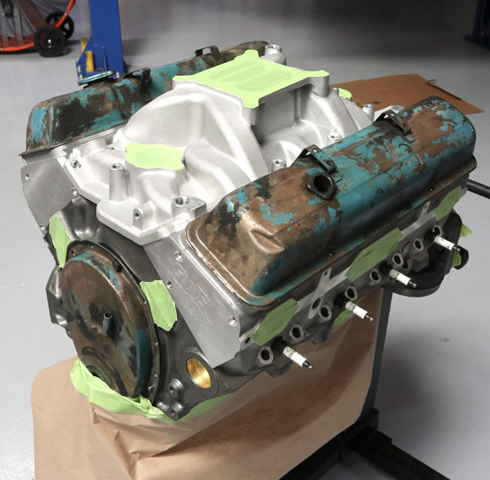
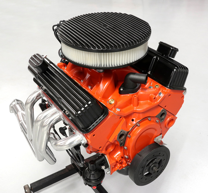
Our goal for this build is a simple small-block that has a classic—but not totally stock—look, makes good power, and actually sounds the part. We’d also like to drop it into our ’69 Nova without having to whip up an entirely new recipe when it comes to fitment, fuel delivery, and wiring. Maybe we’ll go EFI in the future, maybe we’ll put a hotter roller cam in it, or more hard-core cylinder heads, but for now we just want a solid all-rounder that we can swap in and have some fun with.

'69 Nova in white with black wheels
1. This engine’s eventual home will be our ’69 Nova. The car is currently powered by a wheezy 305ci Chevy that makes just enough torque to get out of its own way (barely). On the plus side, it makes no horsepower, sounds underwhelming, and looks mediocre.
taking out camshaft
2. The first step was installing our hydraulic flat tappet camshaft. We made sure to coat all the lobes in a generous amount of camshaft break-in lube to protect them during the first startup. Then we used a long bolt threaded into the end of the cam to help give a little extra leverage when installing.
tightening double-roller timing set
3. We proceeded to fit our double-roller timing set, making sure to have the number one piston at the top of its stroke (top dead center) then we lined up the dots on our cam and crank sprockets. When tightening the bolts, make sure to check your recommended torque specs so you don’t overdo it; for us it was just 20 lb-ft.
balls of putty on valve relief
4. Before getting too far ahead of ourselves, we wanted to double-check two things: One is our valve to piston clearance and the other being pushrod length. Before installing one of the cylinder heads, we stuck a small ball of putty in each valve relief.
cylinder head
5. Then we installed the cylinder head and torqued all the bolts to spec in three increments and in their proper sequence.
marking with black sharpie
6. We used a black marker to cover the valve stem tip before installing the lifter, pushrod, and rocker arm to check our pushrod length. Then we turned the engine over a couple full rotations to let the rocker tip leave a good imprint on the valve stem.
marking with black sharpie
7. On Speedway Motors’ listing of our FLOTEK cylinder heads, there is a Question and Answer section where we found the pushrods recommended by the manufacturer. Once we removed the rocker arm, there was a perfectly centered line on the valve stem tip indicating we indeed had the right length for our application.
As it turned out, the bearings Speedway Motors provided with their rotating assembly were a perfect match.
8. After also installing a lifter, pushrod, and rocker arm on the intake valve, we turned the engine over again and then pulled off the cylinder head. We used the depth checker on the other end of our digital micrometer to measure the clearance between the piston and valve on the intake and exhaust sides. As it turned out, we still had over 0.350-inch clearance on each.
engine prepped for paint
9. It was finally time for paint. Our strategy was to temporarily bolt the heads and intake manifold in place. Then we used a combination of old valve covers, timing cover, and spark plugs plus masking tape to protect the parts of the engine we didn’t want painted. To make sure the paint adhered properly, we scuffed all surfaces with a Scotch-Brite pad then cleaned thoroughly with rubbing alcohol.
engine painted in orange color
10. We sprayed the engine with engine primer followed by a few coats of Chevy Red-Orange high-temp engine enamel then let it sit overnight before proceeding to reinstall the cylinder heads for good.
pre-soaking filters
11. Next, we pre-soaked our lifters in engine oil to make sure they were properly lubricated then dropped them into their respective homes. It can also be a good idea to coat the bottom of the lifters in break-in lubricant, but we felt comfortable passing on this step as we were confident in the copious amount of lube we put on the cam lobes.
refilling oil in pushrod
12. Before installing each pushrod, we used our oiling can to fill each pushrod with engine oil. This simply helps cut down the time it takes to get oil up to the top of the valvetrain upon initial startup.
installing rocker arms
13. Then we installed the rocker arm studs and rocker arms. An important note here is that, at least on our cylinder heads, the four middle rocker arm studs on each head penetrated into the water passage and required the use of thread sealant.
setting valve flash
14. Once we squared up the valveguides and rocker arms, we proceeded to set the valve lash. When the valve was closed, we put a half turn of preload on each rocker arm before locking them down with the setscrew.
timing cover seal

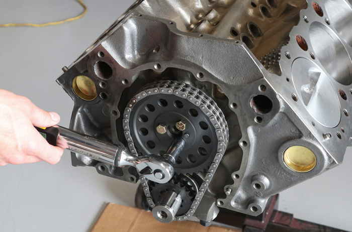
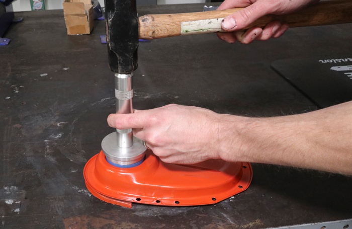
15. Next we used a seal installer (a large, properly sized socket can also do the job) to tap in the timing cover seal before bolting the cover to our block.

black oil pan
16. Before installing any of the Speedway Motors black finned dress-up parts, we took the time to spray a few coats of black semigloss on the oil pan, air cleaner, and valve covers. As shipped, these components come in a flat black coating that can be tough to clean if it gets greasy and tends to fade more quickly. We used 220-grit sandpaper to bring back the brushed fins once the paint dried.
installing oil pan
17. We then went ahead and installed the oil pan using Speedway Motors’ one-piece rubber oil pan gasket. As long as you take your time and make sure everything sets completely, this gasket allows you to avoid the mess of using a silicon sealer and traditional cork gaskets. And, should you ever need to drop your oil pan in the future, the gasket is reusable.
applying thin coat of gray RTV

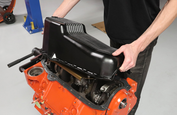
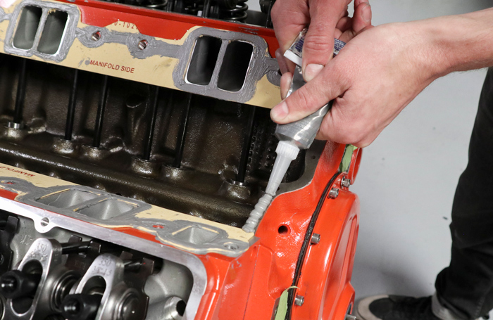
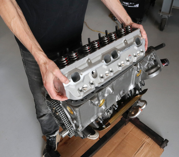
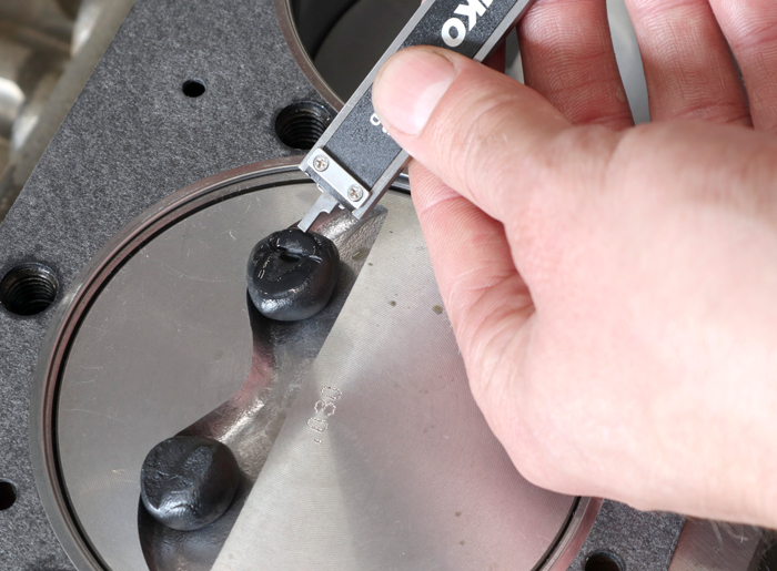
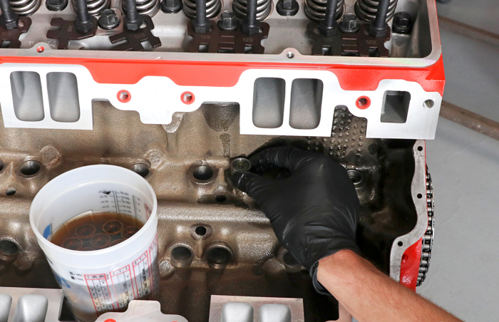
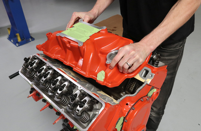
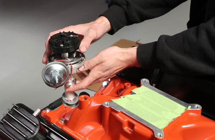
18. Next up, we flipped the engine back over and moved our attention to the intake manifold. The top-end kit comes with an oversized gasket that needs to be trimmed to match the ports of your intake manifold and cylinder heads. Once we tidied up the gasket, we gave each port a thin coat of gray RTV on each side followed by a thick bead along the front and rear edge of the lifter valley.

carefully dropping aluminum intake manifold
19. We slowly and carefully dropped the aluminum intake manifold into place before torqueing it to spec using the supplied hardware.
finned valve covers
20. We bolted down our finned valve covers using a set of Speedway Motors Steel Core Valve Cover Gaskets which, like our oil pan gasket, are reusable and can be installed without RTV.
90 degree swivel
21. Another neat component that comes with the dress-up kit is a 90 Degree Swivel Aluminum Water Neck. It can be installed with the outlet facing in just about any direction needed and seals using an O-ring instead of a paper gasket with RTV.
PerTonix Flame-Thrower distributor
22. With the engine sitting at top dead center on the exhaust stroke, we then dropped in our PerTronix Flame-Thrower distributor and bolted on the ignition coil.
holley 650-cfm double pumper
23. We mentioned earlier that we chose a Holley 650-cfm double-pumper to feed our 383. Reason being, we plan to bolt a manual transmission behind the stroked small-block and having mechanical secondaries helps avoid initial bogging under hard acceleration.
installing headers
24. Then, in preparation for running and terminating spark plug wires, we hung our set of Doug’s full-length headers. After all the time it took to get here, installing the headers also gave us a big dopamine hit—our engine is really starting to look the part!
keeping wiring away from headers
25. We mocked up our Taylor 8mm wires, making sure to route them in a way that keeps them off the headers and down out of sight for a cleaner overall appearance.
crimping spark plug wiring
26. While cheaper spark plug crimping tools are available that utilize a bench vise, we opted to borrow a set of fancy crimpers to terminate the distributor side of our wires. A good tip here is to use a bit of WD-40 to help slide the new boot into place.
engine 90% completed fully assembled
27. After finishing up installing a few odds and ends, like a Speedway Motors mechanical fuel pump, harmonic balancer, and an oil filter, we finally installed our matching air cleaner and took a step back to admire our work.
SOURCES
Holley
(866) 464-6553
holley.com
PerTronix Performance Brands
(909) 599-5955
pertronixbrands.com
SPEEDWAY MOTORS
(855) 313-9173
speedwaymotors.com/allchevyperformance