

 Images BY THE AUTHOR
early all performance automotive magazine stories take the positive approach. We bolt on the parts, the engine makes more power, and the paintjob comes out perfect every time. Everybody wins, the birds sing, and life is grand. But that’s rarely how it works in the real world.
This story begins with gritty facts that unfortunately happen all too often. The owner of the engine in question has requested to remain anonymous mainly because he now feels like he’s been ripped off. It all started when he asked if we could spend a few minutes curing an ignition problem.
The engine in question was not a typical mild street small-block but instead a high-compression street/race small-block Chevy that was aimed at attacking the local eighth-mile dragstrip.
This seemed odd but very little facts were known because the original engine builder had died. Engine details were foggy but the seller claimed it was a 403ci with 13.5:1 compression, a big mechanical roller cam of unknown specs, and good iron 215cc Dart heads. We removed the valve covers to find a Coleman stud girdle and big dual valvesprings.
When we pulled the front timing chain cover, we were surprised to find a Comp roller cam button. Closer inspection revealed that the cam gear protruded from the block roughly 1/4 inch, which radically misaligned the chain to the crank gear. Before disassembly we also checked the cold lash and found it ranging wildly from 0.020 to 0.032 inch!
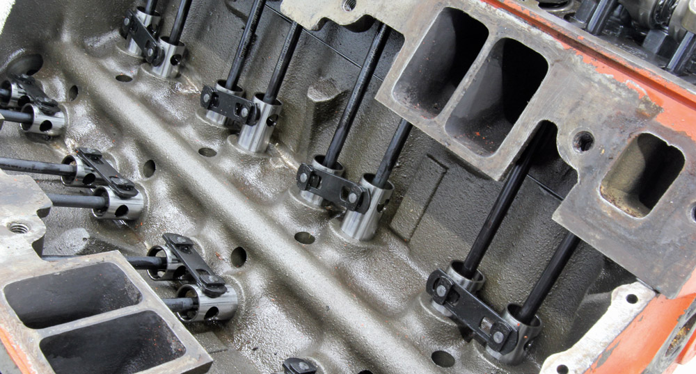
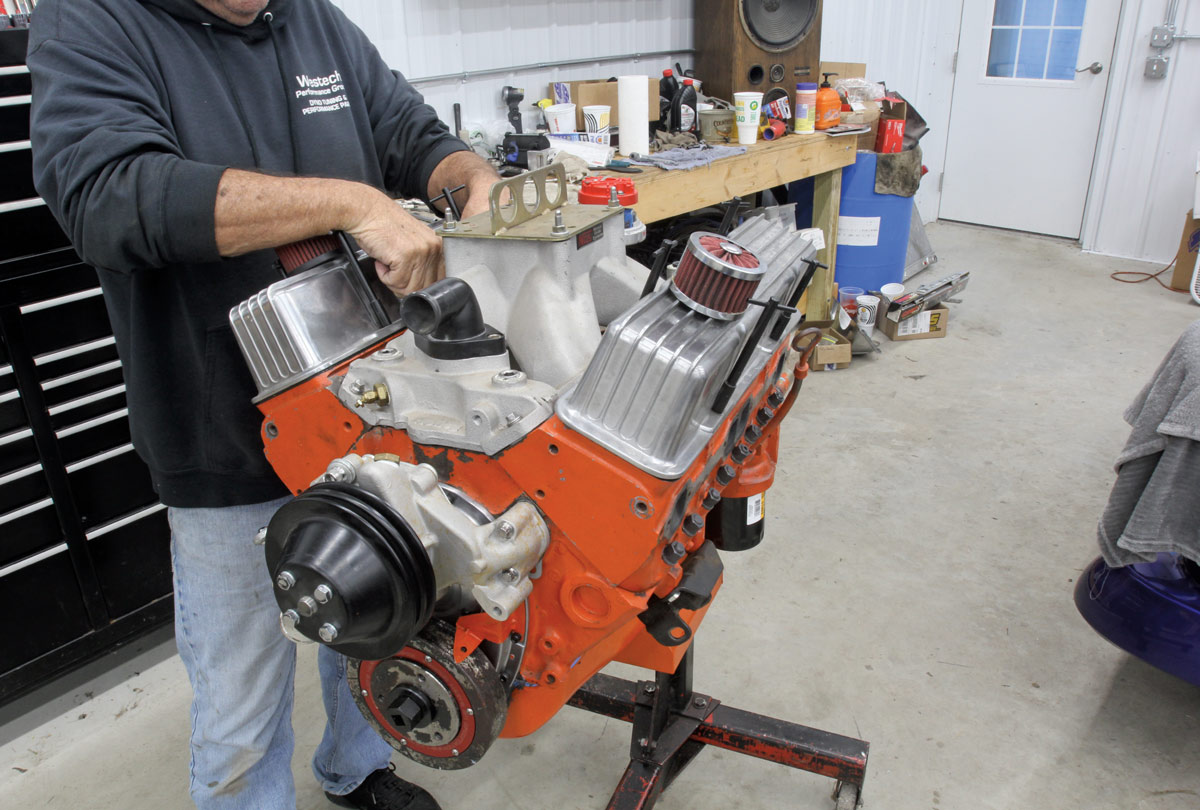
We decided to pull the engine out of the car. With the intake removed we were greeted with an Isky rev kit. For readers not familiar with that term, it was once common to outfit big roller cams with springs between the cylinder head and each mechanical roller lifter.
We decided to yank the cylinder heads to remove the rev kit and discovered all kinds of problems. The original builder used stock head bolts that were under-torqued or had relaxed. We also noticed the head gasket was close to failing between the center cylinders where the heat concentrates on small-blocks.
Worse yet, the head gaskets were for a 4.00-inch bore 350 engine that placed the fire ring into the cylinder. Not good. We also measured the cylinder and combustion chamber volumes and discovered the compression was actually 12.13:1 (see sidebar).
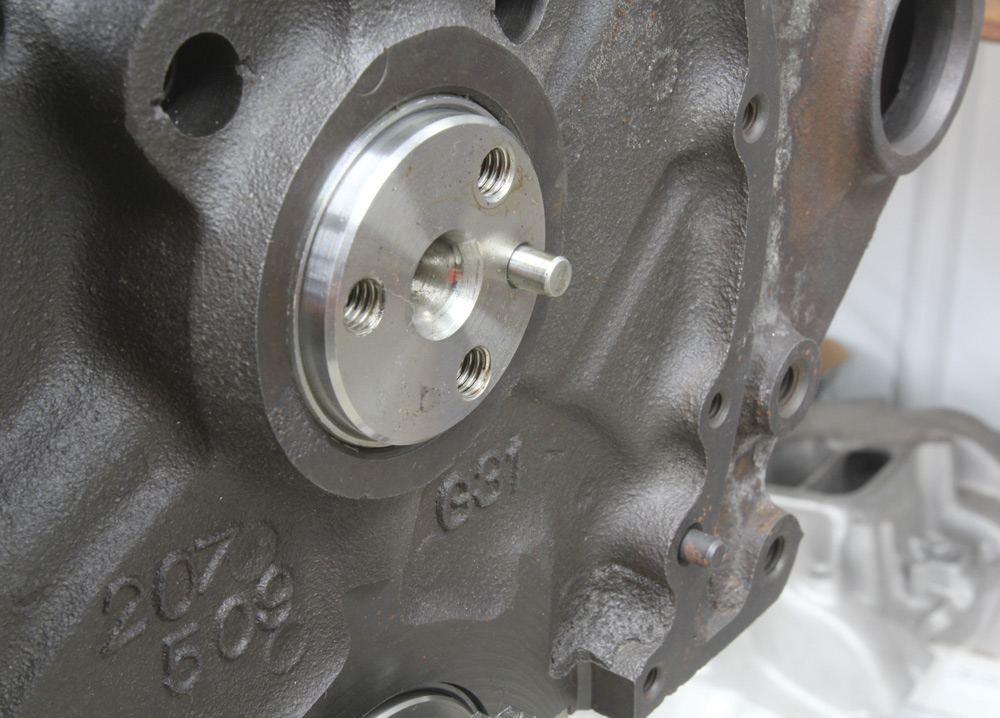
The main issue however was still the improper alignment of the cam and crank timing gears. After we removed the heads, it was clear that the cam was pushed forward because the rear cam plug had been installed too deeply. After thinking about how this blunder could have occurred, we think that someone installed the cam plug in the back of the block at the very last and drove it in too far, forcing the cam (with the cam button) forward, bending the stock timing cover. We used a rubber mallet on our camshaft installation tool to drive the cam (and rear plug) backward until the cam face was flush with the front of the block.
We then ran through the process of finding the cam’s opening and closing points at 0.050-inch lobe lift, which gave us duration on the intake and exhaust. It’s possible the numbers are not 100 percent accurate but they are close enough to give us an idea of the size of the cam. A Summit online cam program crunched the numbers for us and produced 254 degrees of intake duration at 0.050-inch lobe lift with 258 degrees on the exhaust and roughly 0.610-inch valve lift at zero lash using light checking springs.
We decided to retain the camshaft but to replace the rev kit lifters with more modern Comp Cams mechanical roller lifters. We checked the net valve lift with the new lifters, the big springs, new Comp pushrods, and ARP rocker studs with the stud girdle in place with 0.020 inch of cold lash. This produced a max valve lift at a lower 0.570 inch. Part of this change in lift includes the 0.020 inch of lash along with roughly 0.020 inch of valvetrain deflection from the high spring pressure.
We also installed checking springs on Number One cylinder and checked the valve-to-piston (V to P) clearance. The intake side was too close at 0.070 inch while the exhaust enjoyed more room at around 0.140 inch at zero lash.
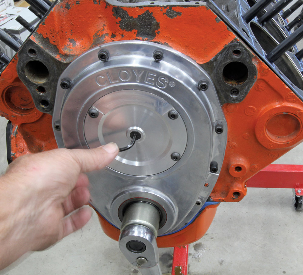
To improve the intake V to P we retarded the cam 4 degrees with the Cloyes crank gear, which added intake P to V clearance but also tightened up the exhaust side with 0.120 inch for both the intake and exhaust. We finished up with a new Cloyes aluminum cover that allowed us to easily set cam endplay.
While disassembling the heads to check the valvespring pressure, we discovered several broken valve locks. We replaced them all with new Comp 10-degree locks. This damage probably occurred when the engine was revved to 7,500 rpm on several occasions. We informed the new owner that we felt this engine should now not spin past 6,500 until we have some time on the engine to establish if the valvetrain is stable. We also checked TDC on the balancer and found it off by about 2 degrees, so we changed the zero mark on the balancer and marked a new location for 36 degrees total advance.
After we ran the engine on our Summit Racing test stand, we delivered it to Tom Kirchhoff’s Performance Auto in Waterloo, Iowa, to run on their Stuska dyno to produce some actual power numbers. We really didn’t expect too much from this small-block, but we were hoping to see 520 lb-ft of torque and 550 hp.
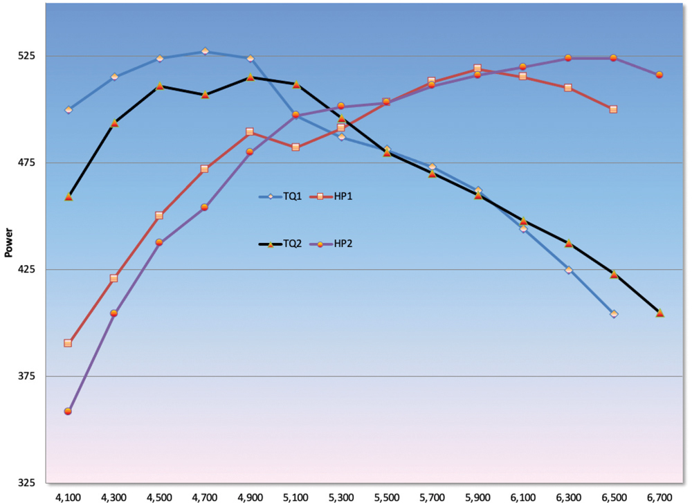
Dyno day was disappointing but not unexpected. After setting the timing at an indicated 36 degrees, the engine ran well using Sunoco 110 race gas. The 403 managed to pump out an encouraging 528 lb-ft of torque at peak at 4,800 rpm but could only manage 519 hp at 5,900. Revving past 6,000 rpm pushed the engine into what appeared to be serious valve float, and the power numbers plummeted. We agreed with dyno operator Curt Wollin who suggested that it would probably be best to stop running the engine until we fixed this problem.
The dyno curve also revealed a serious dip in the torque curve that indicated to us a loss of valve control prior to the peak horsepower point. The solution to this problem was to dial in a different, shorter duration mechanical roller cam.
At least that’s what we thought would solve the problem. But it turned out we were wrong.
We went back to the shop, disassembled the engine and removed the original mystery cam. The cam we chose was selected out of expediency—we had one sitting on the shelf. The cam chart will give you the details, but the short version is that it was 12 degrees shorter in duration on the intake side and 10 degrees on the exhaust with slightly less lift. We also put it in at 108-degree intake centerline instead of 106 thinking that would help the top-end power.
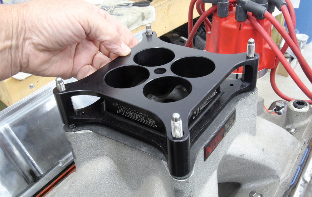
We reused the lifters, pushrods, rockers, and valvesprings after closely inspecting the locks to make sure none had been damaged. All looked good. With everything buttoned back up, we also decided to change to a different intake. We dumped the original single plane in favor of a Holley Strip Dominator. In previous testing we found this Holley manifold is both affordable and generally better at peak horsepower and average torque than most other single-plane intakes. We retained the original 850-cfm Holley Street HP carburetor.
We began the second dyno day with much anticipation because we thought we now had control over the valvetrain. We expected the peak torque numbers to be substantially better than the previous test’s 527 lb-ft peak number.
That didn’t happen.
Instead, the engine suffered a massive loss of both torque and horsepower. The first pull barely made 480 hp at 6,000 rpm and the torque was off by 60 lb-ft. If that wasn’t bad enough, the dip in the power curve remained. Something was seriously wrong.
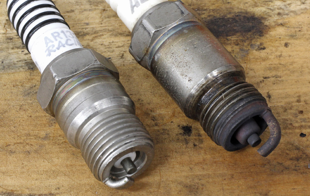
We had set the ignition timing at 36 degrees so Wollin suggested we add more timing. We added 4 degrees and the power jumped dramatically. We added another 4 degrees and power improved again. The timing indicated on the balancer was 44 degrees BTDC, which was clearly not accurate. We inspected the spark plugs and noted that the color on the ground strap revealed the timing was close to optimal.
We then tried adding a 1.5-inch Wilson carb spacer between the Holley manifold and the 850 carburetor and this helped slightly with a gain of roughly 4 to 5 hp through most of the entire curve. However, the torque curve still exhibited a slight depression at 4,700 rpm that we were never able to eliminate. At least now the engine was positively responding to changes.
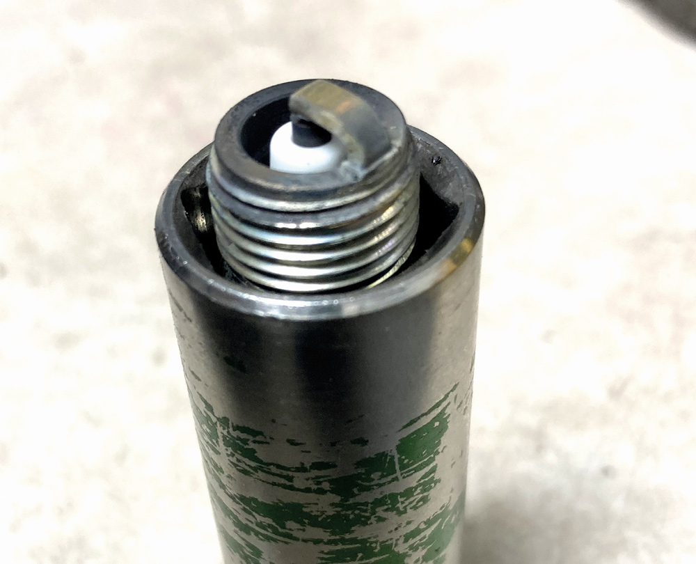
Wollin had yet another recommendation. His experience on big-piston dome engines revealed they responded to using non-projected nose spark plugs. Our engine was fitted with projected nose plugs, so this was an easy change. The engine improved again by an average of 4 lb-ft of torque throughout the entire curve and produced 525 for peak horsepower at 6,400 rpm with a peak torque of 515 lb-ft at 4,900.
These are similar numbers to our first test but a comparison of the torque curve from the big-cam test versus this second small-cam test revealed that we lost torque with the smaller camshaft. Wollin suggested that we go back to the original cam to improve the overall power. Now that we know that the first test suffered from retarded ignition timing, the larger cam would obviously now make a bunch more power.
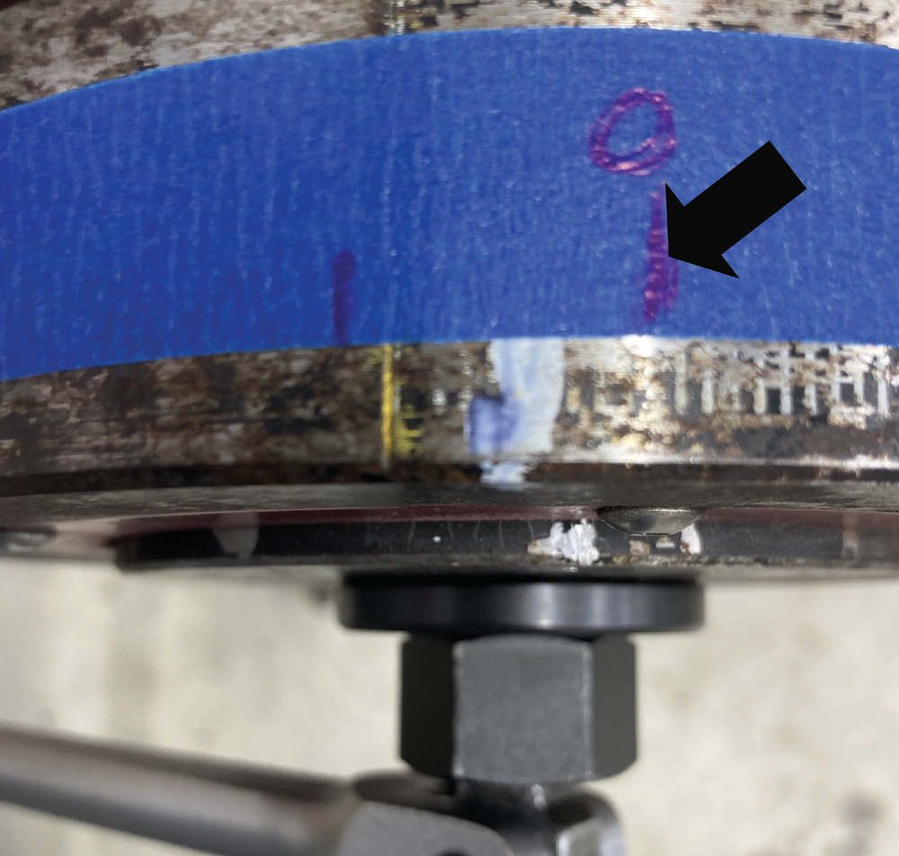
With 44 degrees showing on the balancer, it was clear that the harmonic balancer outer ring had slipped. We had checked the location of top dead center (TDC or 0 degrees on the balancer) before the first test session and found it was off by 2 degrees, which we assumed was only a minor error.
After returning to our shop, we checked TDC again and we found the outer ring of the balancer had moved by 7 degrees. So just within the dozen or so pulls on the dyno, the balancer ring had moved an additional 5 degrees! This means that while the indicated timing was at 44 degrees, the true timing was only 37 degrees BTDC. We started the first dyno session with the big cam with probably only 30 to 31 degrees of total timing and that was why the engine performed so poorly.
We will now replace the harmonic balancer with a new SFI unit and double check our TDC mark again to ensure that the ignition timing indicated on the balancer is absolutely correct.
Our big mistake was not adding ignition timing to the engine on the first dyno session. Had we tried that we might have realized the harmonic balancer was not accurate and the engine would have certainly made much more power. The first session made only 519 hp at 5,900 because the late ignition timing was holding it back. We’re fairly certain this engine can make 540 to 550 hp with the bigger camshaft combined with proper ignition timing.
The error of not adding more ignition timing in the first dyno session was based on our concern that the valvetrain was in distress and it might drop a valve because of the broken valve locks we had found.
If this was a made-for-TV movie, we would run the engine one more time with the bigger cam and make hero power. But that’s not going to happen because the owner has already spent over $1,000 on testing. Sure, it would be nice to know but sometimes the realities of blue-collar finances muscle their way into the conclusion of a good story.
Overall, we did radically improve this small-block’s power and reliability. The two biggest issues we repaired were the cam shoved too far forward and the demonic harmonic balancer. The plan now is to reinstall the original camshaft, re-verify P to V clearance, and stuff the engine back in the car so the owner can put all his newfound power to use. This process took much longer than it should have to uncover this small-block’s flaws and it seemed like a battle the entire way.
This was a little like a detective story where the mechanical sleuths had to root out all the clues, find the culprits, and put them away. As usual, it was a learning experience and hopefully what we discovered can be put to use the next time you’re faced with a similar situation. Let’s just hope you uncover your problems much quicker than we did.
We then measured the actual cylinder volume again placing the piston 0.200-inch down in the cylinder. This produced 45 cc, which is 1 cc larger than our calculated cylinder volume. Even though the piston has a dome, it also sports very deep valve reliefs, which essentially offset the dome volume. The result is something very close to a pure flat-top piston with a 1 cc valve relief.
We used these numbers to calculate the compression ratio with a 4.135-inch bore, a 3.75-inch stroke, a 62cc chamber, a piston with the equivalent of a 1cc valve relief, a 0.010-inch deck height, and a compressed head gasket thickness of 0.041 inch. The combination of a 0.010-inch deck height and a 0.041 gasket pushes the quench to 0.052 inch, which is quite wide and further lowers the compression. All these factors combine to produce a 12.13:1 compression ratio.

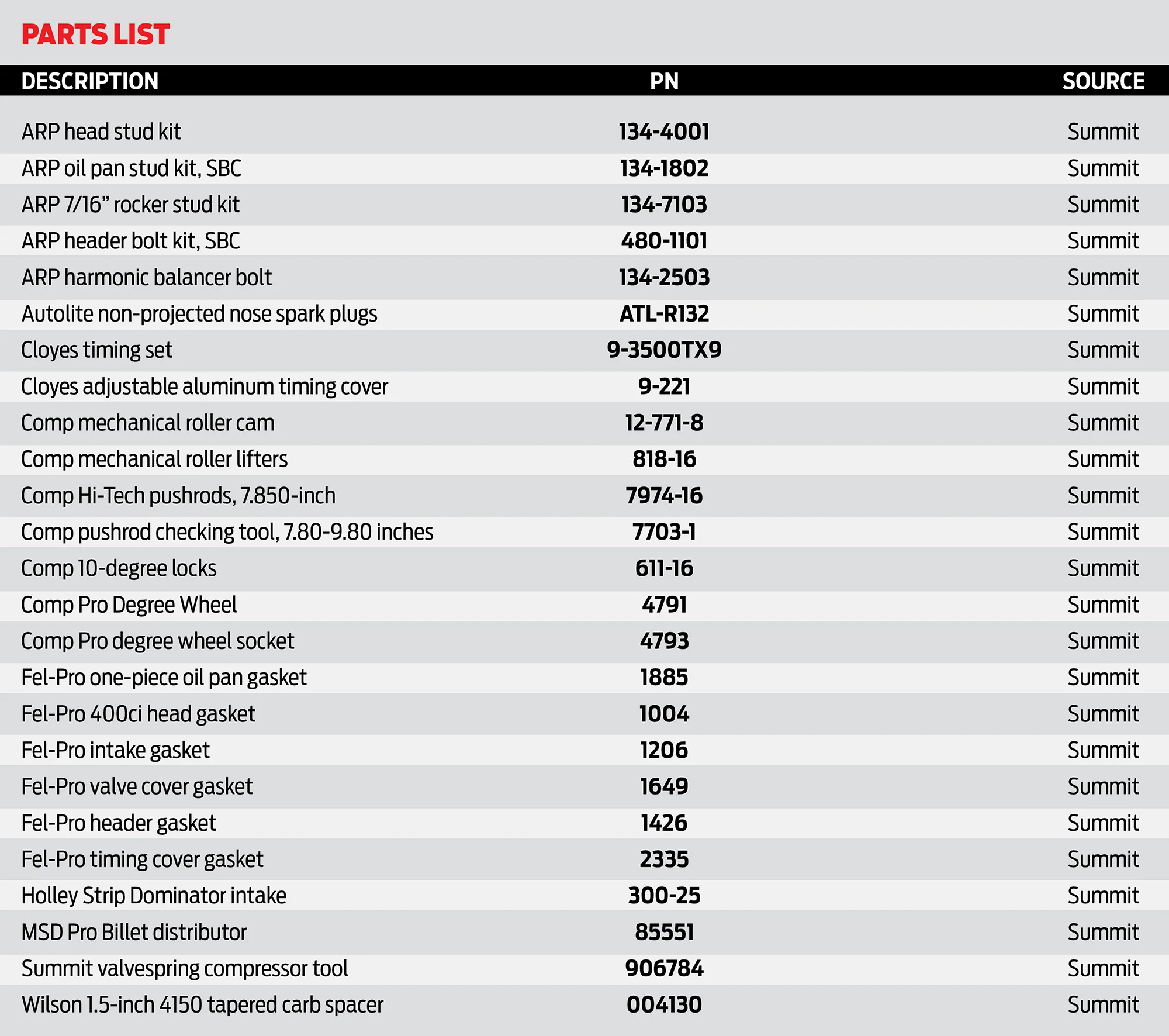


 SOURCES
(319) 291-6580