ACP department heading TECH
InTheGarageMedia.com
A Firmer Foundation typographic title in white
A Firmer Foundation
Strengthening The First-Gen F-Body Structure with Detroit Speed Subframe Connectors

By Barry Kluczyk Photography by THE AUTHOR

S

tructural rigidity has long been the Achilles heel of unibody cars—particularly cars from the muscle car era, such as the first- and second-generation Camaro. The issue becomes more acute with a significant jump in performance when greater horsepower and handling capability expose the functional boundaries of the body structure.

A weaker structure is not only prone to metal fatigue and even ripping in some areas, but it makes it more difficult to put all the car’s power to the pavement, whether in a straight line or in corners. It’s simply impossible to optimize launches or handling with excessive chassis flex.

So, just as long as there have been flexible unibodies, subframe connectors and other structural enhancements have been the cure—but even they have had their compromises. Typically, they’ve necessarily followed the contours of a car’s floor, which often means less-than-optimal strength. Also: Following the underside of the floorpan often reduces ground clearance while also creating somewhat of an unsightly profile.

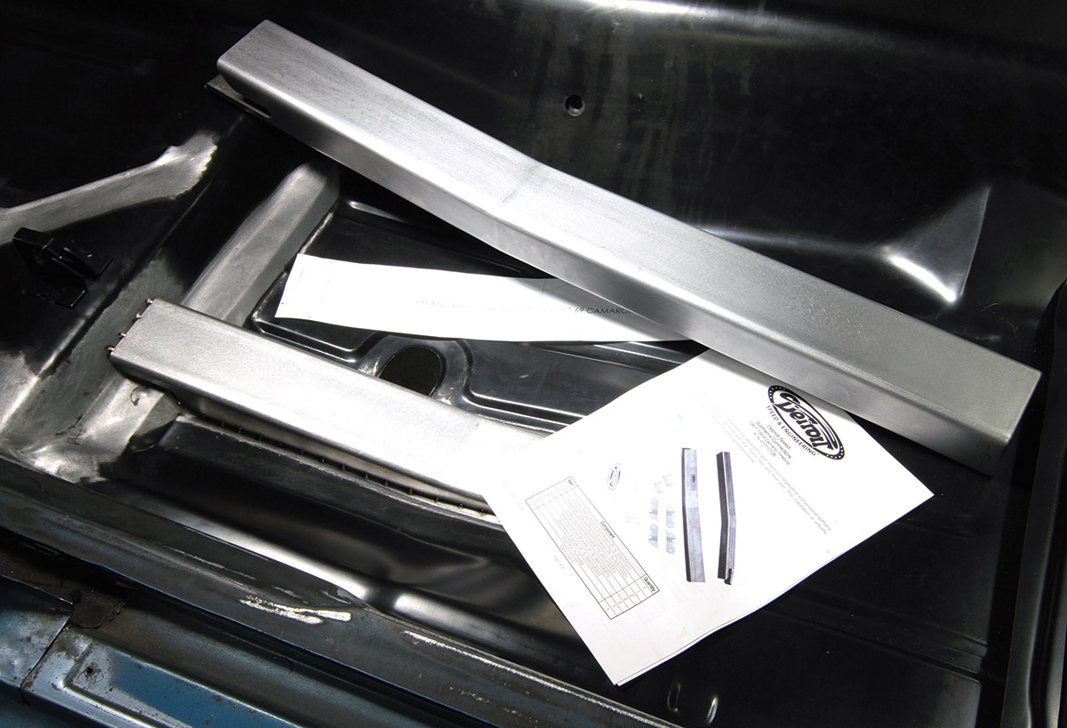
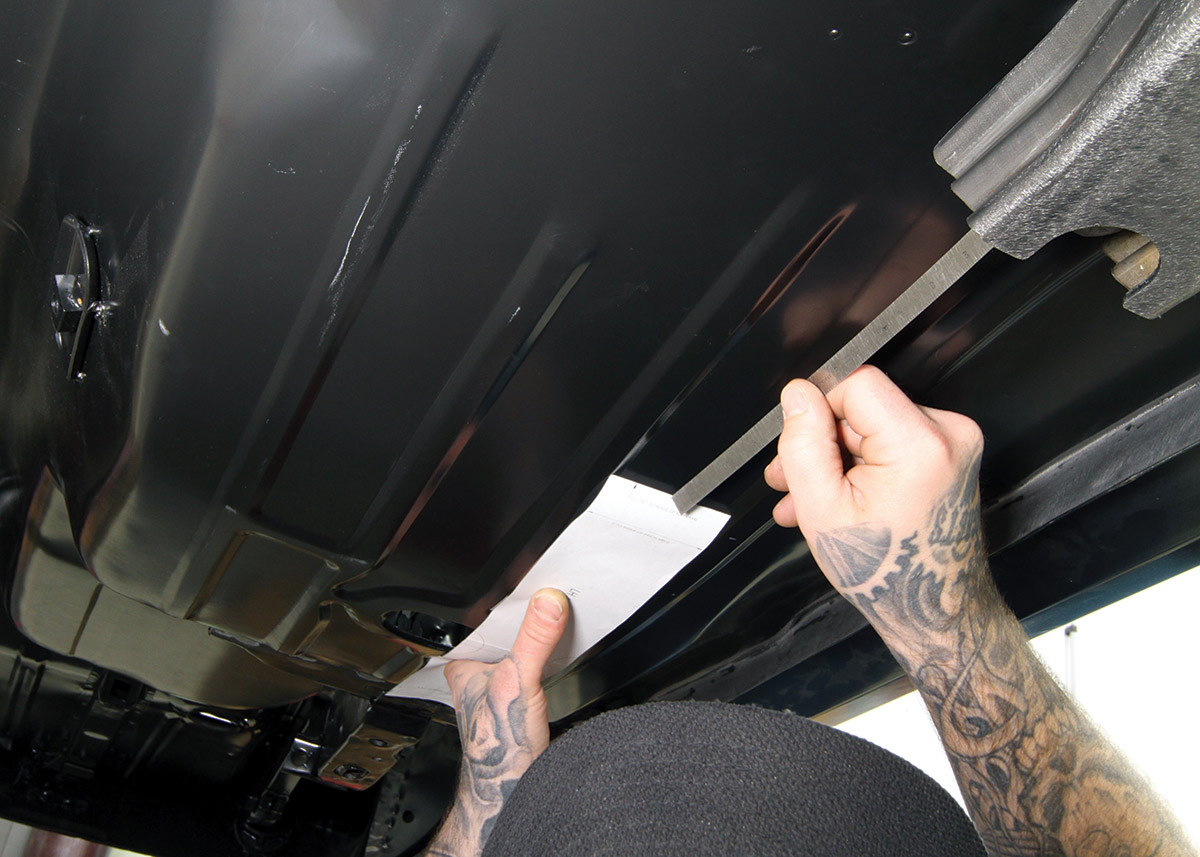
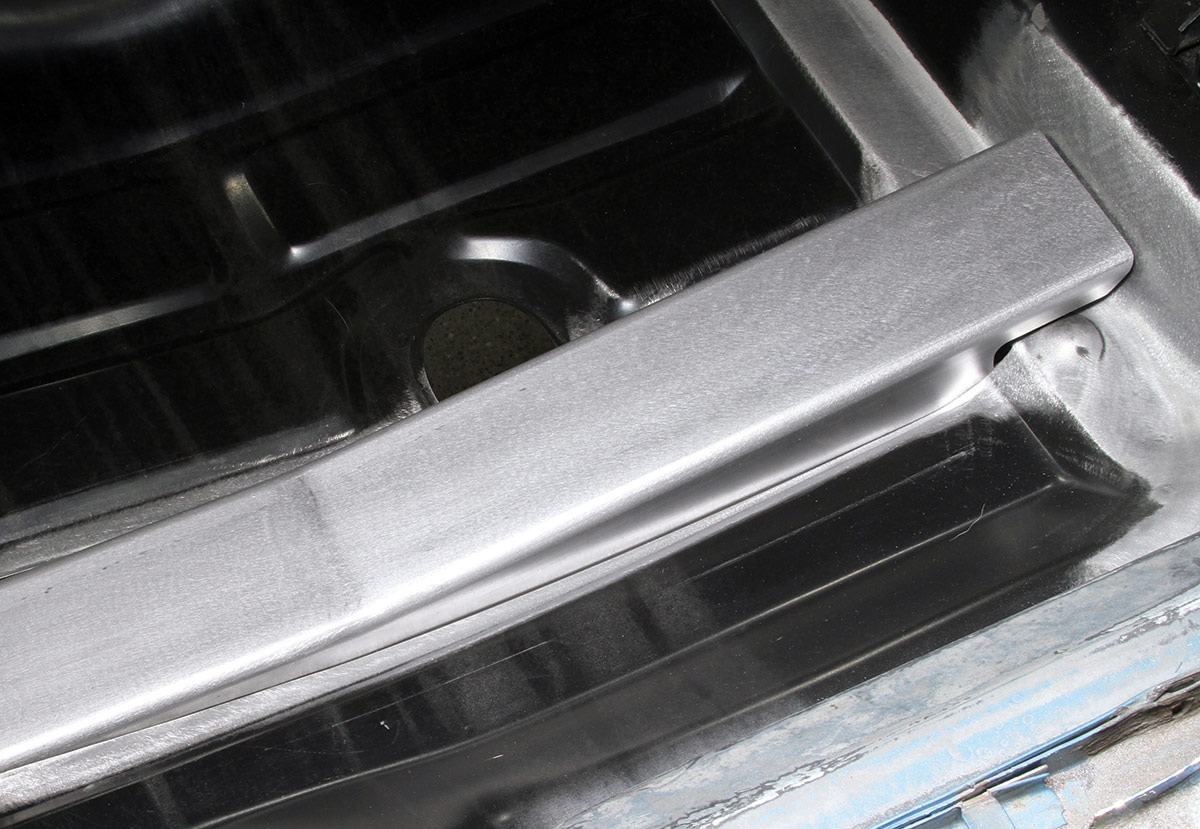
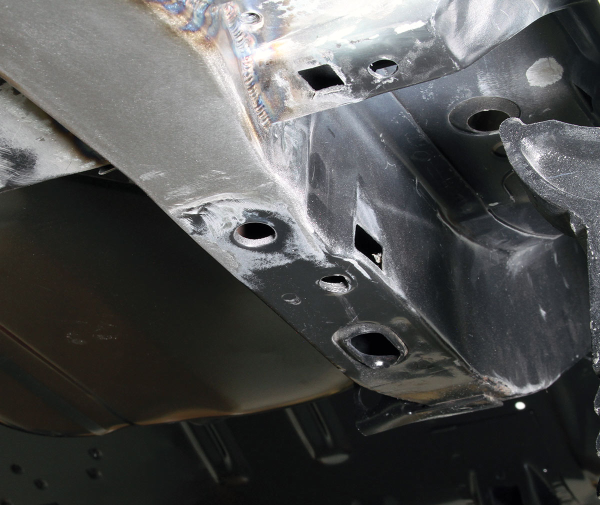
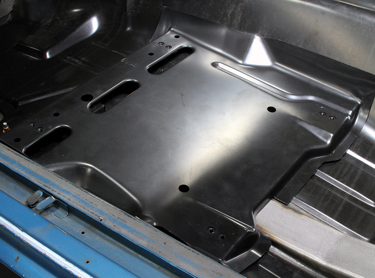
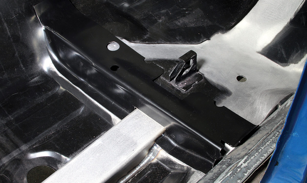
That’s where Detroit Speed’s (DSE) first-gen F-body subframe connectors differ. Rather than compromising strength and ground clearance, they literally cut through the floorpan to create a straighter, more rigid, lower-profile link between the front subframe and rear framerails.

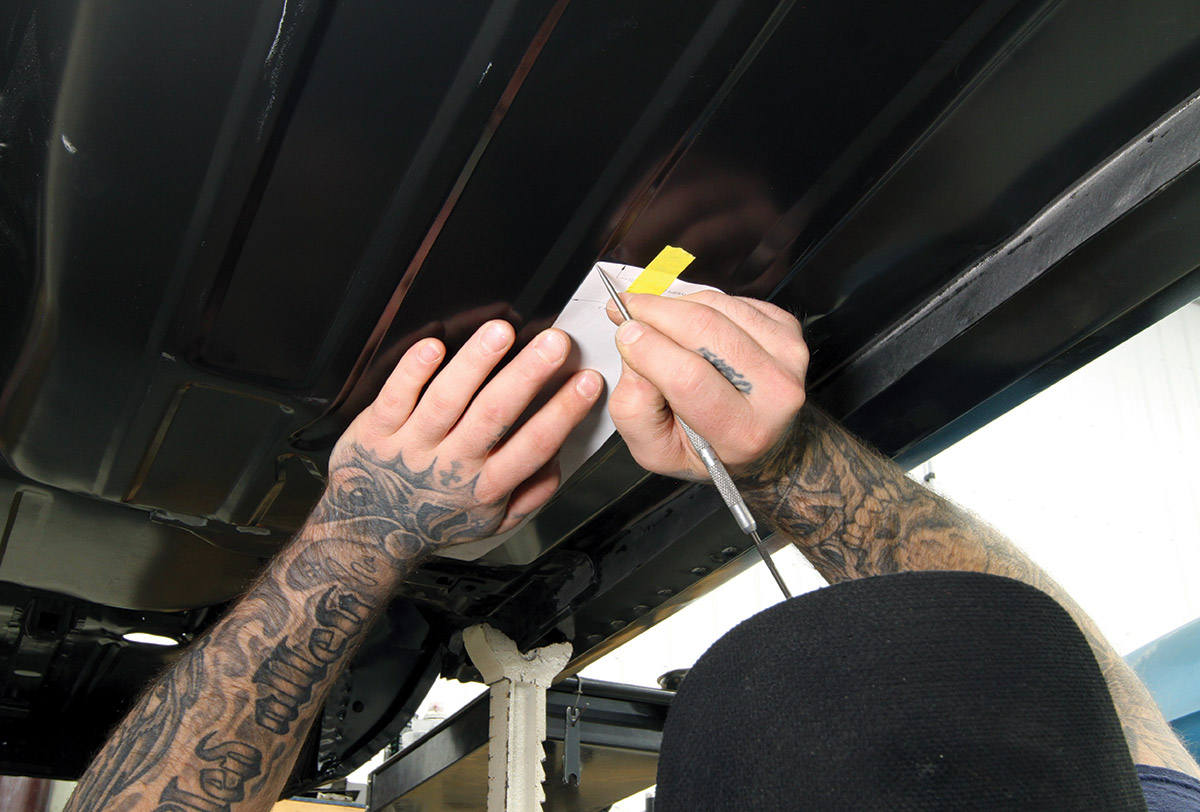
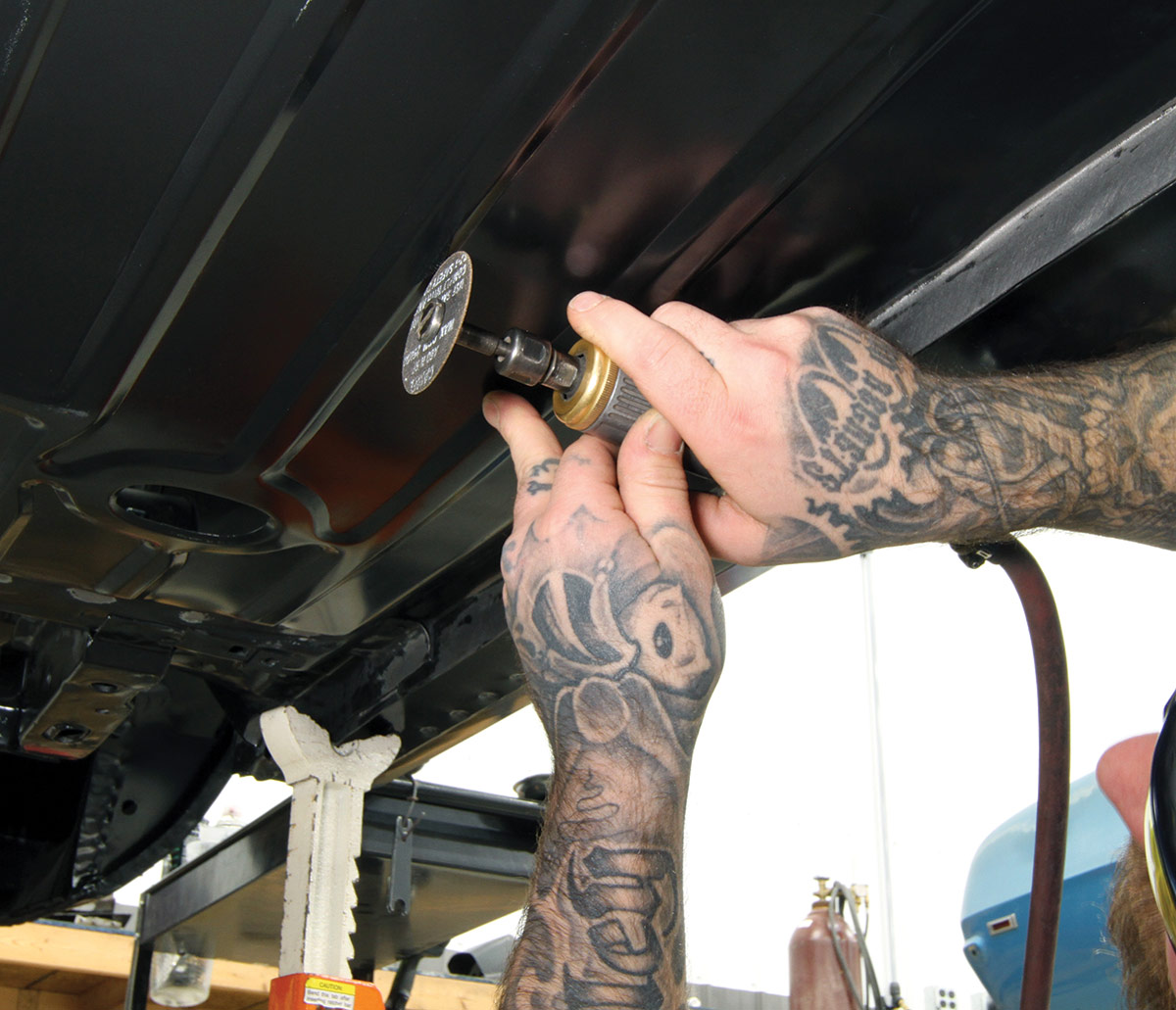
Let’s be clear about that: Installing DSE’s subframe connectors requires cutting holes in the floor. Fortunately, they do not interfere with the rear seat mounts in coupe or convertible models, but in addition to the holes to be cut in the floor, the installation also requires notching the front seat risers on both body types as well as the reinforcement plates on convertibles.

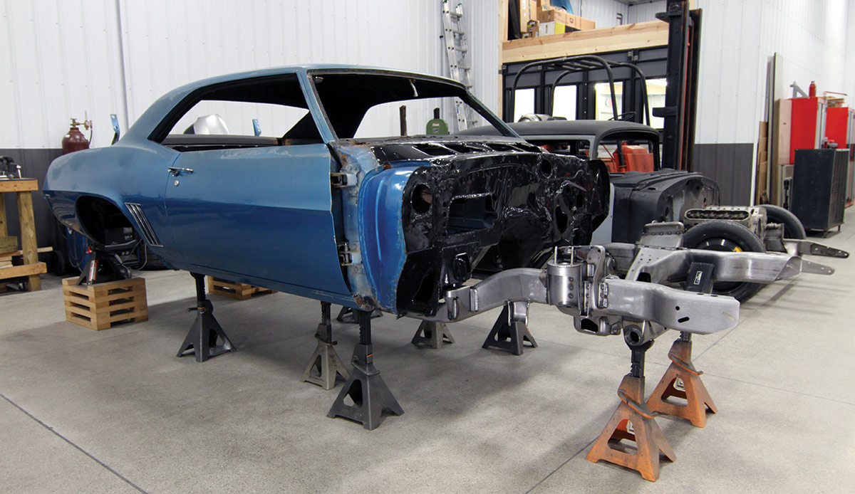
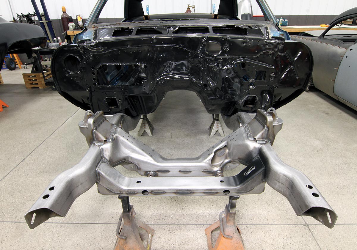
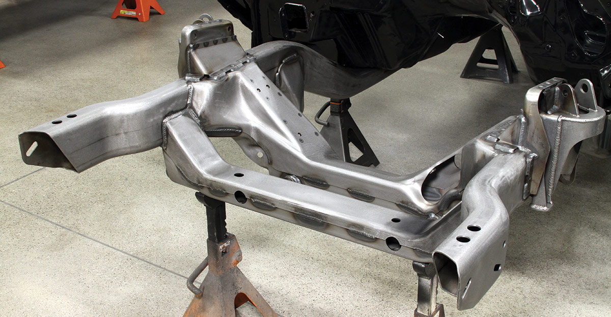
We recently followed the installation at Sled Alley where the job was being performed on Mark Stielow’s latest ’69 Camaro project—the one in which we’ve already covered its complete floor replacement. It also just received a new, bolt-on DSE front subframe.

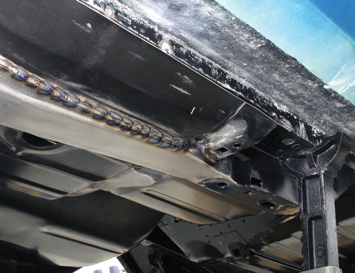
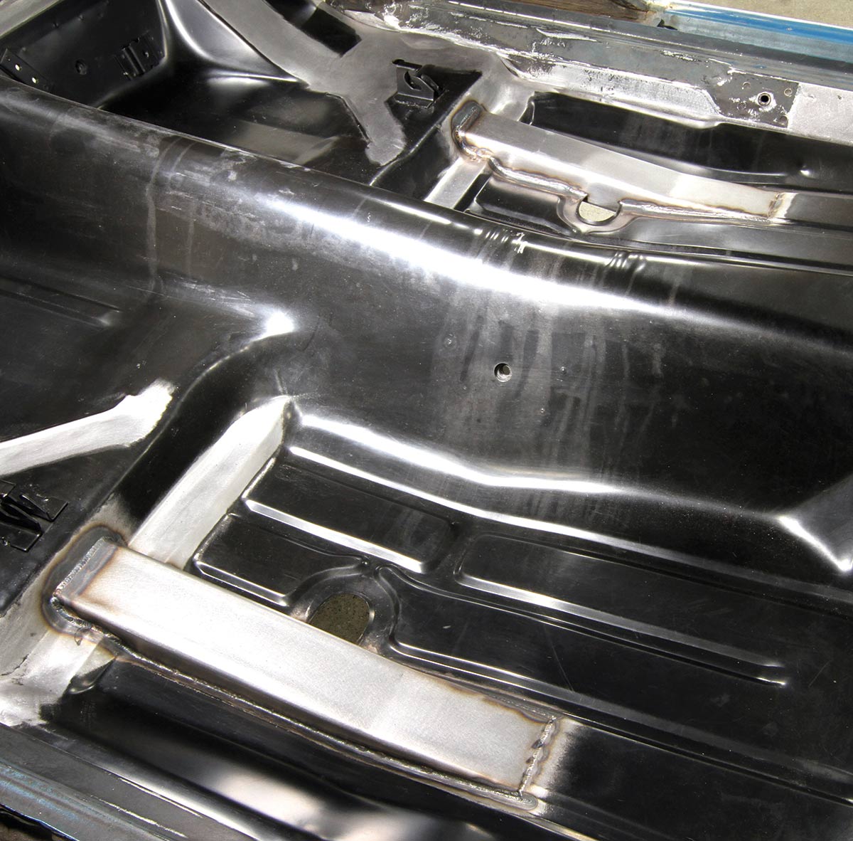
“Even though you’re cutting into the floor, it’s the most effective way to build strength into the body,” Sled Alley’s Matt Gurjack says. “The connectors’ rails don’t intrude much into the floor and the carpet fits right back over them.”

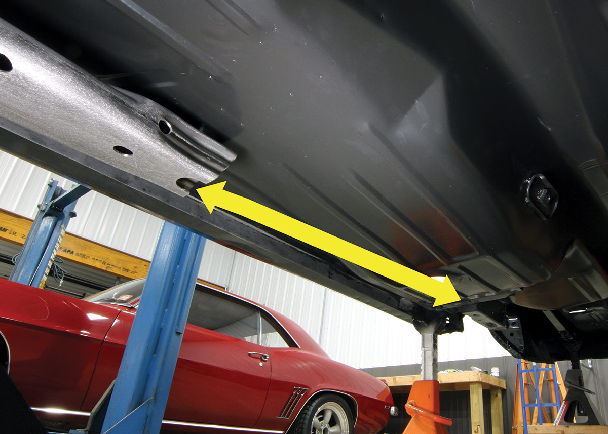
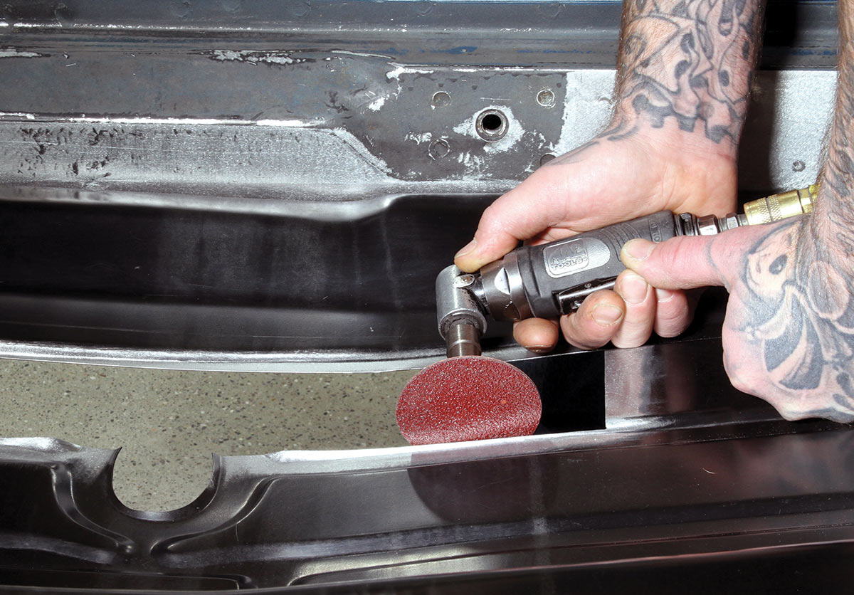
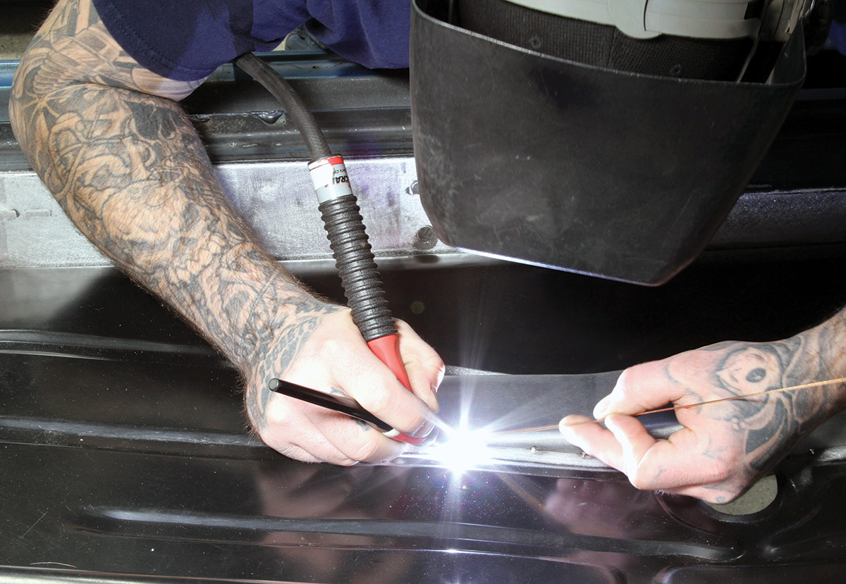
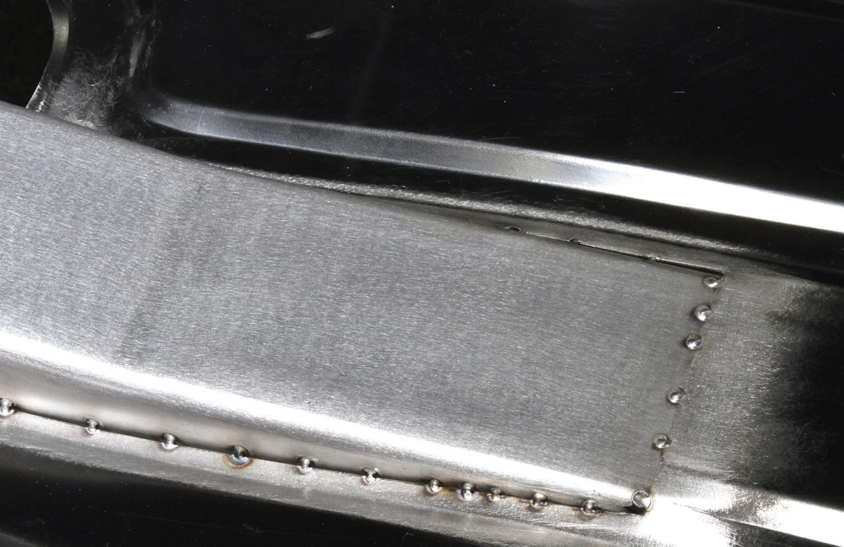
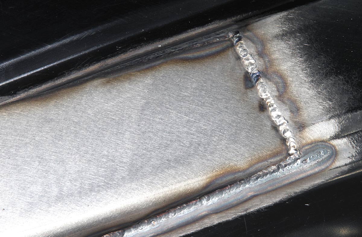
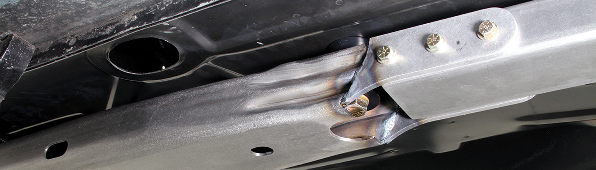
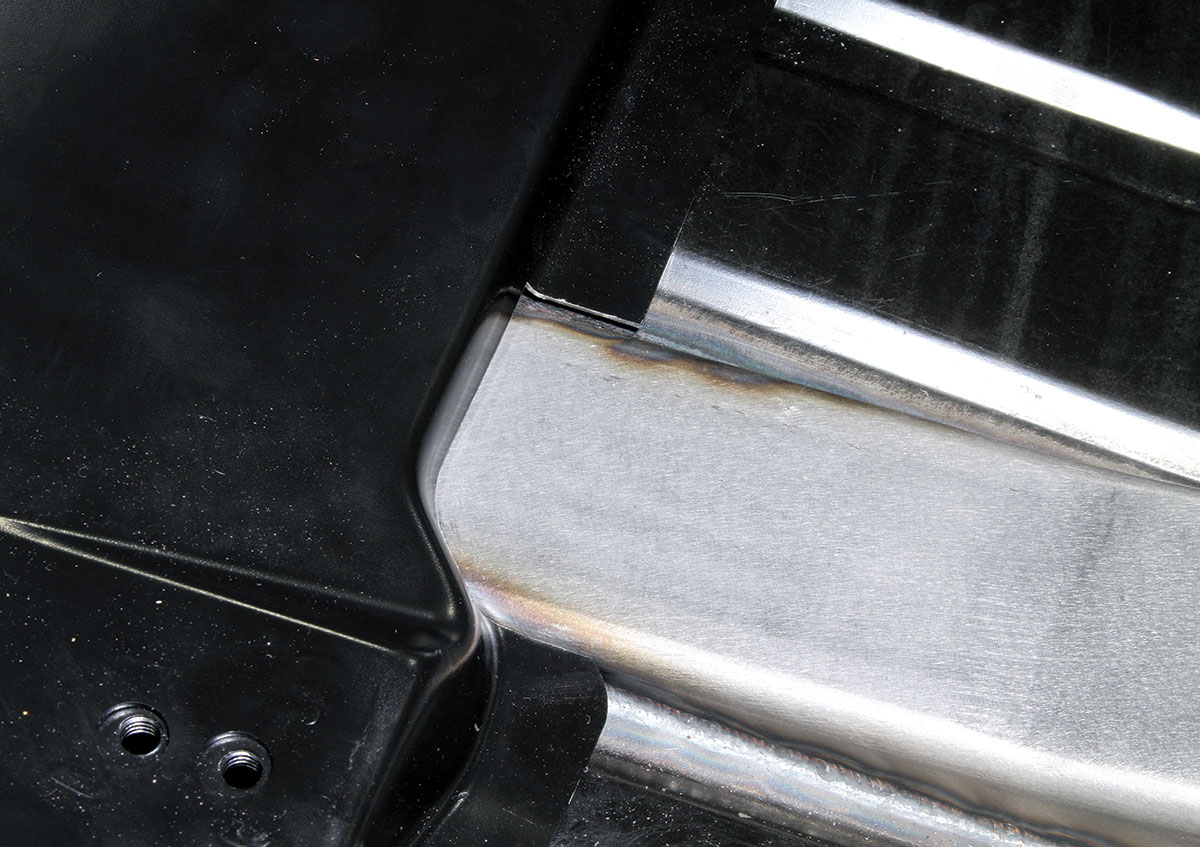
Notably, the rear of the connectors are welded to the rear framerails, while the frontends are bolted in place, allowing the front subframe to remain removable. The portions of the connectors that protrude into the interior are welded to the floorpan, further enhancing the overall strength of the upgrade.

If adding these connectors to an already running-and-driving car it’s going to require pulling out the interior for the job. The brake and fuel lines should also be removed because, you know, it all involves welding in their vicinity. The more practical approach, as seen on Stielow’s car, is to bake their installation into a project that already required stripping back the body to its bare shell.

Either way, it’s the smartest and most effective way to add crucial strength to the F-body’s body structure—strength that will absorb a more Pro Tourer or restomod’s horsepower, while also making sure those ponies stay in line around the bends. If you’re adding big power or handling capability to your early F-body, this upgrade is a must.

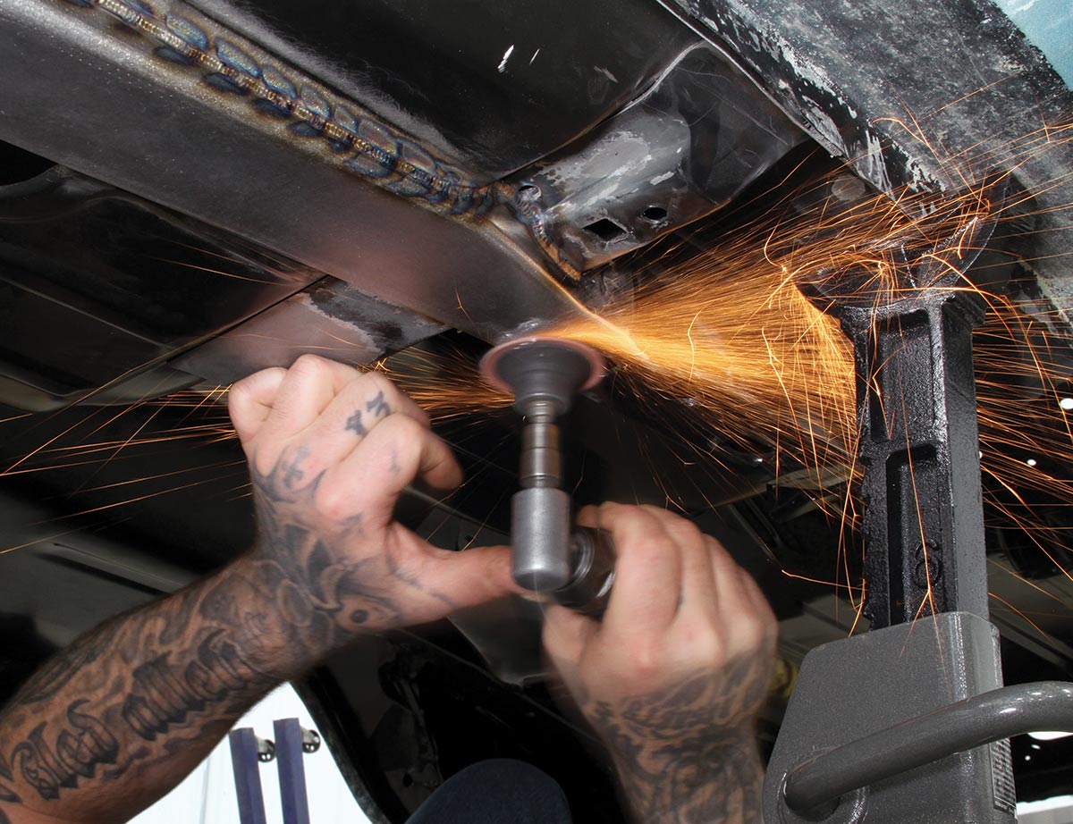
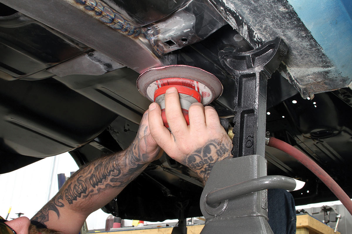
Follow along as we provide an overview of the installation procedures.

We’re back on the build stage of Mark Stielow’s latest Pro Touring project, a ’69 Camaro that spent its early years as a dedicated drag car. It’s now headed for the street and occasional run around a road course. In the previous installment, we covered the replacement of the floor, which now wears a new DSE front subframe.
1. We’re back on the build stage of Mark Stielow’s latest Pro Touring project, a ’69 Camaro that spent its early years as a dedicated drag car. It’s now headed for the street and occasional run around a road course. In the previous installment, we covered the replacement of the floor, which now wears a new DSE front subframe.
Like the original front subframe, the DSE subframe bolts to the unitized body but provides a stronger platform for the powertrain and is designed for more contemporary suspension choices.
2. Like the original front subframe, the DSE subframe bolts to the unitized body but provides a stronger platform for the powertrain and is designed for more contemporary suspension choices.
Subframe connectors are the logical next step in the car’s upgrades, as they link the front subframe to the rear framerails, providing a stiffer, more rigid foundation suited to its planned performance capability. They’re made from 2x3-inch rectangular steel, with tapers at the rear to match the rear-seat part of the floorpan. Templates are included for the holes required to be cut into the floor.
3. Subframe connectors are the logical next step in the car’s upgrades, as they link the front subframe to the rear framerails, providing a stiffer, more rigid foundation suited to its planned performance capability. They’re made from 2×3-inch rectangular steel, with tapers at the rear to match the rear-seat part of the floorpan. Templates are included for the holes required to be cut into the floor.
The connectors will create a rigid link between the bolt-on front subframe and the integrated rear framerails. The project is easier when the body, like this one, is completely disassembled and there are no brake or fuel lines in the way. The same goes for the seats, carpet, and trim on the inside of the car. The installation will also require trimming of the seat risers.
4. The connectors will create a rigid link between the bolt-on front subframe and the integrated rear framerails. The project is easier when the body, like this one, is completely disassembled and there are no brake or fuel lines in the way. The same goes for the seats, carpet, and trim on the inside of the car. The installation will also require trimming of the seat risers.
The project starts by holding up the templates supplied by DSE to locate the proper position for the holes to be cut into the floor. Measurements are provided regarding their proper placement.
5. The project starts by holding up the templates supplied by DSE to locate the proper position for the holes to be cut into the floor. Measurements are provided regarding their proper placement.
With the templates taped in place, lines are scribed around them, providing guidelines for cutting.
6. With the templates taped in place, lines are scribed around them, providing guidelines for cutting.
Then, a cut-off wheel is used to slice through the comparatively thin floor. Sled Alley’s Matt Gurjack suggests cutting just inside the lines to provide a slightly smaller opening at first, as it is easier to add clearance with a little grinder than correct for a too-large gap.
7. Then, a cut-off wheel is used to slice through the comparatively thin floor. Sled Alley’s Matt Gurjack suggests cutting just inside the lines to provide a slightly smaller opening at first, as it is easier to add clearance with a little grinder than correct for a too-large gap.
With one of the holes cut, its sharp edges are quickly ground down in preparation for fitting the connector.
8. With one of the holes cut, its sharp edges are quickly ground down in preparation for fitting the connector.
Next, the connector is slipped into the hole in preparation for welding. Note the C-shaped notch at the rear, which overrides the top of the floorpan inside the car, while the corresponding bottom edge butts against the rear framerail.
9. Next, the connector is slipped into the hole in preparation for welding. Note the C-shaped notch at the rear, which overrides the top of the floorpan inside the car, while the corresponding bottom edge butts against the rear framerail.
Cutting the hole just a hair closer helped deliver an extremely precise fit within the floor for welding. With the connector located, it simply needs to be held in place by a jackstand or similar for welding.
10. Cutting the hole just a hair closer helped deliver an extremely precise fit within the floor for welding. With the connector located, it simply needs to be held in place by a jackstand or similar for welding.
MIG or TIG welding is suitable for the job. Sled Alley elected for TIG welding here, mostly for the control and lack of follow-up grinding. Because the material of the connector is so much thicker than the floorpan, Matt Gurjack flows the metal from the connector down into the floorpan. It makes for a clean, stronger connection that doesn’t burn through the thinner-gauge floor.
11. MIG or TIG welding is suitable for the job. Sled Alley elected for TIG welding here, mostly for the control and lack of follow-up grinding. Because the material of the connector is so much thicker than the floorpan, Matt Gurjack flows the metal from the connector down into the floorpan. It makes for a clean, stronger connection that doesn’t burn through the thinner-gauge floor.
Here are the basic tack welds that hold the connector in place. After this, it’s simply a matter of filling in the welds around the perimeter. It’s a time-consuming and painstaking process that requires great attention to detail.
12. Here are the basic tack welds that hold the connector in place. After this, it’s simply a matter of filling in the welds around the perimeter. It’s a time-consuming and painstaking process that requires great attention to detail.
Here’s the completed welding on the top side. There’s no need to grind down the welds but after the project is completed, the exposed metal will, of course, be treated with epoxy to prevent corrosion and be prepped for painting.
13. Here’s the completed welding on the top side. There’s no need to grind down the welds but after the project is completed, the exposed metal will, of course, be treated with epoxy to prevent corrosion and be prepped for painting.
After the connector is welded on top of the floor, the same thing happens on the bottom side. Importantly, the installation does not interfere with the rear leaf spring pockets, making their installation and removal as easy as it was before the connectors were installed.
14. After the connector is welded on top of the floor, the same thing happens on the bottom side. Importantly, the installation does not interfere with the rear leaf spring pockets, making their installation and removal as easy as it was before the connectors were installed.
Grinding was used to eliminate the welded seam between the framerail and the connector.
15. Grinding was used to eliminate the welded seam between the framerail and the connector.
A DA sander was then used to smooth the metal around joined areas.
16. A DA sander was then used to smooth the metal around joined areas.
Like the metal on the inside, the bottom of the connector and framerail section will need to be sealed and prepped for painting, but the end result of the welding and grinding shows integration of the connector and framerail that looks like a factory structural element.
17. Like the metal on the inside, the bottom of the connector and framerail section will need to be sealed and prepped for painting, but the end result of the welding and grinding shows integration of the connector and framerail that looks like a factory structural element.
At the front of the connector, the only welded portions included a couple of brackets that attached to the front subframe. That allowed the connector to be bolted to the subframe (with crush tubes inserted in the connector for strength), preserving the removability of the subframe.
18. At the front of the connector, the only welded portions included a couple of brackets that attached to the front subframe. That allowed the connector to be bolted to the subframe (with crush tubes inserted in the connector for strength), preserving the removability of the subframe.
Even though it’s not welded to the subframe connectors, the DSE front subframe is stronger than the original and still provides a crucial structural enhancement when attached to them. The result is a much more rigid body structure.
19. Even though it’s not welded to the subframe connectors, the DSE front subframe is stronger than the original and still provides a crucial structural enhancement when attached to them. The result is a much more rigid body structure.
Although the connectors are welded in place, there are additional finishing touches, including notching the seat risers that attach to the floorpan. In our previous story that covered the floor replacement, we noted that the risers were left uninstalled in anticipation of the subframe connectors’ installation.
20. Although the connectors are welded in place, there are additional finishing touches, including notching the seat risers that attach to the floorpan. In our previous story that covered the floor replacement, we noted that the risers were left uninstalled in anticipation of the subframe connectors’ installation.
Here’s a closer look at the notch cut in the driver seat riser. A similar cut is needed for the passenger-side riser. If the risers are already installed, larger cutouts are required in order to provide sufficient room for welding around the connectors.
21. Here’s a closer look at the notch cut in the driver seat riser. A similar cut is needed for the passenger-side riser. If the risers are already installed, larger cutouts are required in order to provide sufficient room for welding around the connectors.
Likewise, the floor reinforcements on convertible models must also be notched to accommodate the connectors. This car is a coupe but because the replacement floor from AMD included the reinforcements in the kit, they will be installed to provide just a bit more additional strength. Also, of note here is the fact the connectors do not interfere with the rear seat mounts.
22. Likewise, the floor reinforcements on convertible models must also be notched to accommodate the connectors. This car is a coupe but because the replacement floor from AMD included the reinforcements in the kit, they will be installed to provide just a bit more additional strength. Also, of note here is the fact the connectors do not interfere with the rear seat mounts.
The seat risers and convertible reinforcements still need to be welded in place, but here are the DSE connectors welded in place. They protrude only a little into the rear floor area, but not enough to affect carpet installation. The design not only creates a stronger structure but it does so with a lower profile and no significant effect on ground clearance.
23. The seat risers and convertible reinforcements still need to be welded in place, but here are the DSE connectors welded in place. They protrude only a little into the rear floor area, but not enough to affect carpet installation. The design not only creates a stronger structure but it does so with a lower profile and no significant effect on ground clearance.
SOURCES
AUTO METAL DIRECT
(888) 255-3895
autometaldirect.com
DETORIT SPEED INC.
(704) 662-3272
detroitspeed.com
SLED ALLEY HOT RODS
(586) 630-0171
sledalley.com