
Get That Booster Right
Wilwood Takes the Guesswork out of Making Power Brake Boosters Work
 Images by THE AUTHOR
ot rodding is all about improving the breed. It might be a move like dumping those spindly, 9.5-inch drum brakes on a 1966 Chevelle in favor of four-wheel discs along with adding a power brake booster to make the whole driving experience a little bit easier.
That’s all well and good until the brakes don’t work right. Either the brake pedal feels spongy or the brakes drag so badly the car won’t move. Clearly, there’s a problem, but where to look? Wilwood engineers have had to deal with this often enough that they created a simple little tool to prevent you from singing the “Gimme a Brake” blues.
Like all good automotive ideas, once you see the simplicity around this tool, you’ll think “Why didn’t I think of that?”
The variables begin to stack up when you consider the dozens of different power brake boosters and master cylinders that could be employed. Here’s what can happen. Our friend finds a power brake booster at the swap meet and later combines it with a master cylinder. He bolts it all together and after driving the car for a few miles the front disc brakes heat up and pretty soon the brakes are locked solid. After everything cools down he can limp home with no clue how to fix the problem.
What has happened is the pushrod exiting the power brake booster is too long and when the master cylinder is bolted in place, the pushrod pushes slightly on the master cylinder piston which creates hydraulic pressure even though the brake pedal is not applied.
Wilwood came up with a solution to this dilemma with a simple tool that is shaped like a capital “H.” One side is designed to measure the depth of the recess in the master cylinder piston while the opposite side of the tool compares that to the output length of the apply pin with the power brake booster. The common position for the two measurements is the mounting flange for the master cylinder to the booster.
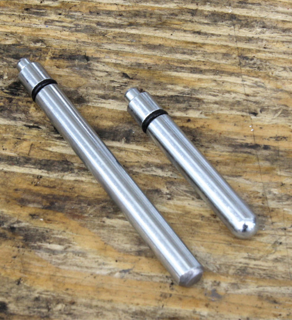
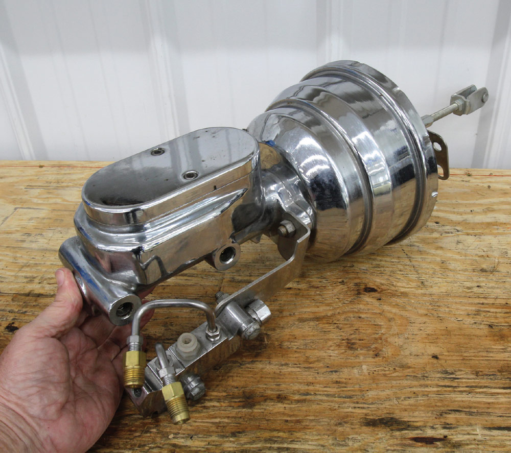
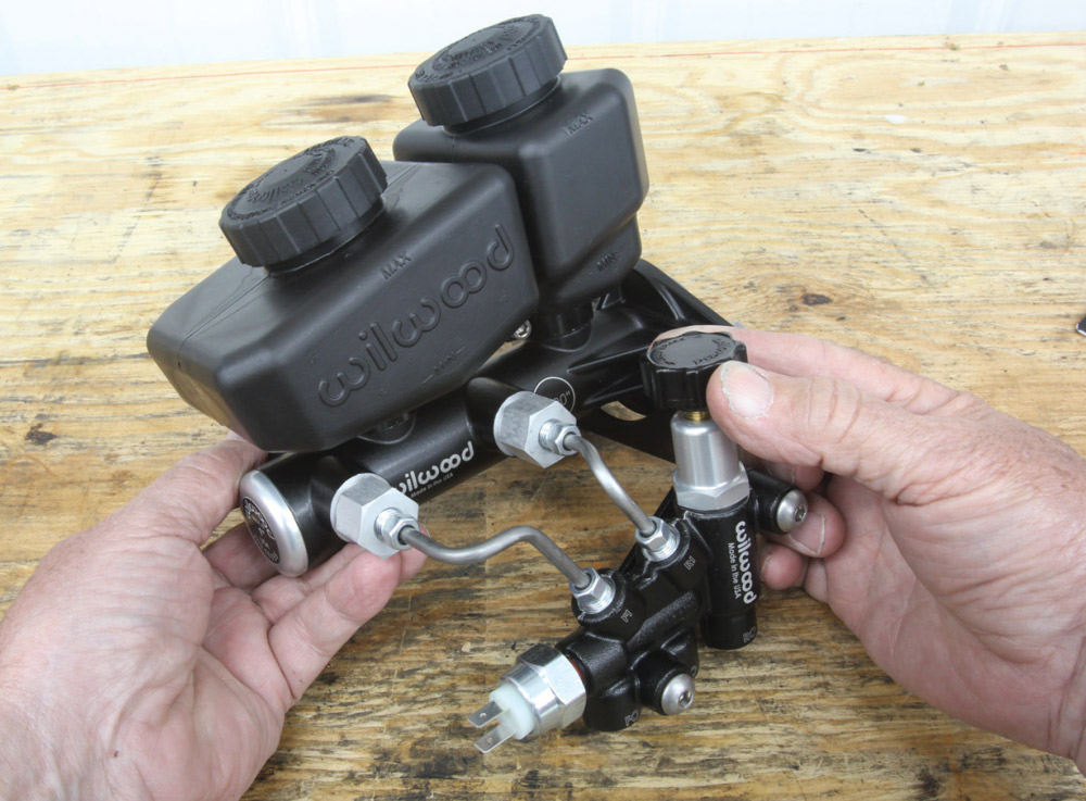
Wilwood shipped us a master cylinder and a tool and we ordered a power brake booster from Classic Performance Products (CPP) for our Chevelle. With all the parts on the work bench, the first thing we noticed was the CPP booster came with two different fixed-length pushrods. It was obvious from the depth of the hole in the Wilwood master cylinder that the short pushrod would not even come close, so we exchanged it for the long pushrod.
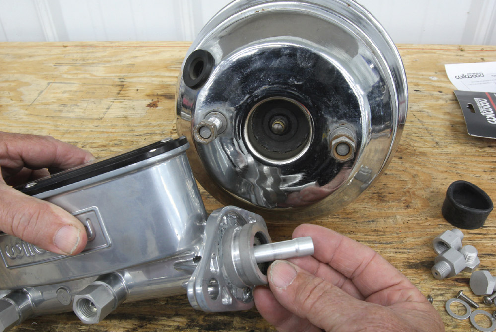
The Wilwood tool is marked with one side to measure the booster and the other for the master cylinder. Also, it’s important to make sure the rounded end of the adjustable slide pin is pointed toward the master cylinder. This is intended to simulate the pushrod from the booster. We located the tool over the piston end of the master cylinder and slid the rod into the recess until it bottomed out. Then we tightened the simple lock screw to hold the pin in place.
Next, we flipped the tool around so that the opposite end faced the power brake booster. The booster side of the Wilwood tool includes two small magnets that hold the tool firmly against the booster to free up both hands so you can measure the clearance between the tool pin and the booster pushrod. In our case, the Wilwood tool would not sit flush on the booster because the pushrod was slightly too long.
This required a simple dressing on the grinder and polisher wheel to shorten the length of the working end of the pushrod. After a couple of grinding sessions, we snuck up on shortening the pushrod. The final session produced a clearance of about 0.015 inch between the pushrod and the working end of the tool after shortening the pushrod perhaps 0.040 inch. Wilwood’s clearance spec is between 0.010 and 0.030 inch. This prevents the pushrod from engaging the master cylinder piston until the brake pedal is applied.
If the booster pushrod has to be modified, try to keep within this spec. Excessive clearance (more than 0.030 inch) only means the pedal will move a greater distance before the pushrod engages the master cylinder piston. This figure of 0.030 inch may not seem like much but keep in mind that this is multiplied by the pedal ratio. With a pedal ratio of 5:1, the pedal is moving 0.150 inch—which is more than 1/8 inch—which might be noticeable.
We checked another brake booster just for kicks and discovered a different issue. This booster used an adjustable pushrod using a small threaded rod. In this case, the rod was way too short with insufficient length to adjust to where we needed it to be. So, we added the Wilwood insert into the master cylinder recess. This insert is included with all Wilwood master cylinders, performing the same job as extending the pin in the booster.
Remeasuring using the Wilwood tool indicated that the pushrod in the master was now too long even when adjusted all the way into the booster. We could have modified the male end of the insert for the master but instead we decided to shorten the actual metric pushrod slightly until we produced 0.020-inch clearance between the pushrod and the insert in the master cylinder. Problem solved.
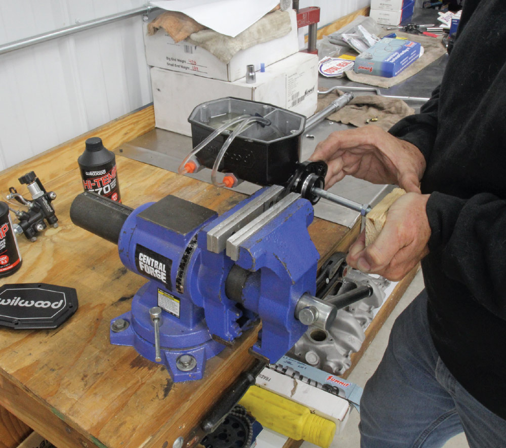
This is also a good place to mention that if you are replacing the existing master cylinder with a new one, this is a perfect opportunity to bench bleed the master cylinder. It might be tempting to skip this step and just bleed the air out of the master on the car, but this can cause problems, especially in power brake booster applications.
Often the master will sit at a rather sharp angle when bolted to the booster. This can cause an air pocket to form in the master cylinder piston bore when bleeding the master in the car. This is why Wilwood always recommends bench bleeding the master horizontally. This allows the bench bleeder kit to purge all of the air out of the master cylinder before it is mounted on the vehicle.
It’s also critical to strong brake performance to properly size the master cylinder piston diameter regardless of whether you are using manual brakes or a brake booster. It’s beyond the scope of this story to dive into all the details, but basically, manual disc brake applications perform best with a smaller master cylinder bore diameter, often less than 1 inch. A smaller piston size generates more pressure for the same pedal effort but will require more pedal travel to produce the necessary volume.
When using power brake boosters, the master cylinder bore diameter is generally 1 or 1 1/8 inch in diameter, which produces less pressure but moves more fluid. The pressure isn’t as critical because the brake booster compensates by increasing the force applied to the master cylinder piston.
One additional point that is important is that power brake boosters need a decent source of manifold vacuum. Engines with idle vacuum levels below 16 inches may present problems with proper boost to the brake pedal. There are kits on the market that will add an electric vacuum pump to the system if insufficient engine vacuum is a problem.
Any strong performance car needs an equally robust brake system, and when it comes to modifying your existing system, it’s best to talk with the experts to get the correct recommendations for your brake system. But using Wilwood’s new booster pushrod tool will certainly get you much closer to producing a solid brake system that is just as strong as that new LS engine you just dropped in the engine compartment.
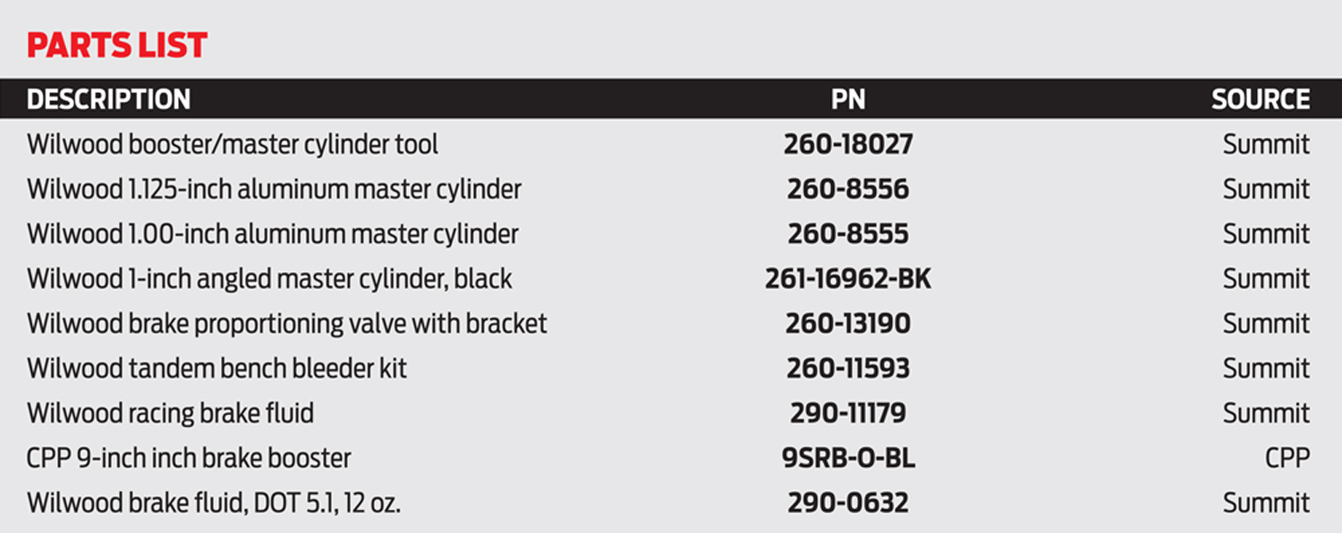


 SOURCES