ACP department heading TECH
InTheGarageMedia.com
Differential Dissidence
Assembling a 9-Inch Rearend for an LS-Powered Tri-Five

By Ryan Manson Photography by The Author

W

hen it comes to upgrading a vintage vehicle to a more modern, more powerful drivetrain, what’s often overlooked are the many components that might require additional attention to ensure said powerplant can deliver the power to the pavement in a safe, reliable manner. Brakes, steering, and suspension are all things that come to mind one might want to upgrade if those items are still stock. But one of the most important items of interest that often gets the last look, is that old, stock rearend. Back in the ’50s, horsepower numbers were still relatively benign and tire options not nearly as aggressive in regards to contact patch and compound as they are today. That meant that the rearend didn’t need to be as stout as one might desire if those tables were turned.

Today, with stock LS crate engine offerings advertising horsepower numbers well above what the beefiest 283 could ever dream of and tire technology and size what it is, upgrading an original rearend is not only a good idea, it’s a near necessity.

Bruce Valley’s ’57 Chevy Handyman Wagon still bore its original rearend when it was rolled into the Clampdown Competition shop, and while we discussed making a handful of upgrades to the stock unit, it was ultimately decided to simply swap it out with a purpose-built 9-inch Ford housing and components from Summit Racing. This tried-and-true combination would be more than capable of handling the power of the 6.2L LS3 crate engine and would allow us to custom-tailor the gearing to suit the overdrive transmission, all the while choosing the strongest components necessary for our application. While we’re at it, we’ll also be taking the opportunity to upgrade the brakes and suspension with a pair of Wilwood disc brakes and Aldan American adjustable shocks that’ll match what we previously installed up front.

While providing every nuanced detail involved in a rearend build will be challenging in magazine form, there are books written on the subject (we recommend CarTech’s Ford Differentials: How to Rebuild the 8.8 and 9 Inch available from Summit Racing). We will, however, definitely do our best to try to address some of the challenges we faced as first-timers. There is no shortage of how-to videos on the interweb; a quick search will bring up a day’s worth of content. Be warned, however, that some are better than others. Assembling a rearend from scratch can be a daunting task, but like any other aspect of a build, when approached with care and patience, it can be done by anyone with a decent set of capable hands!
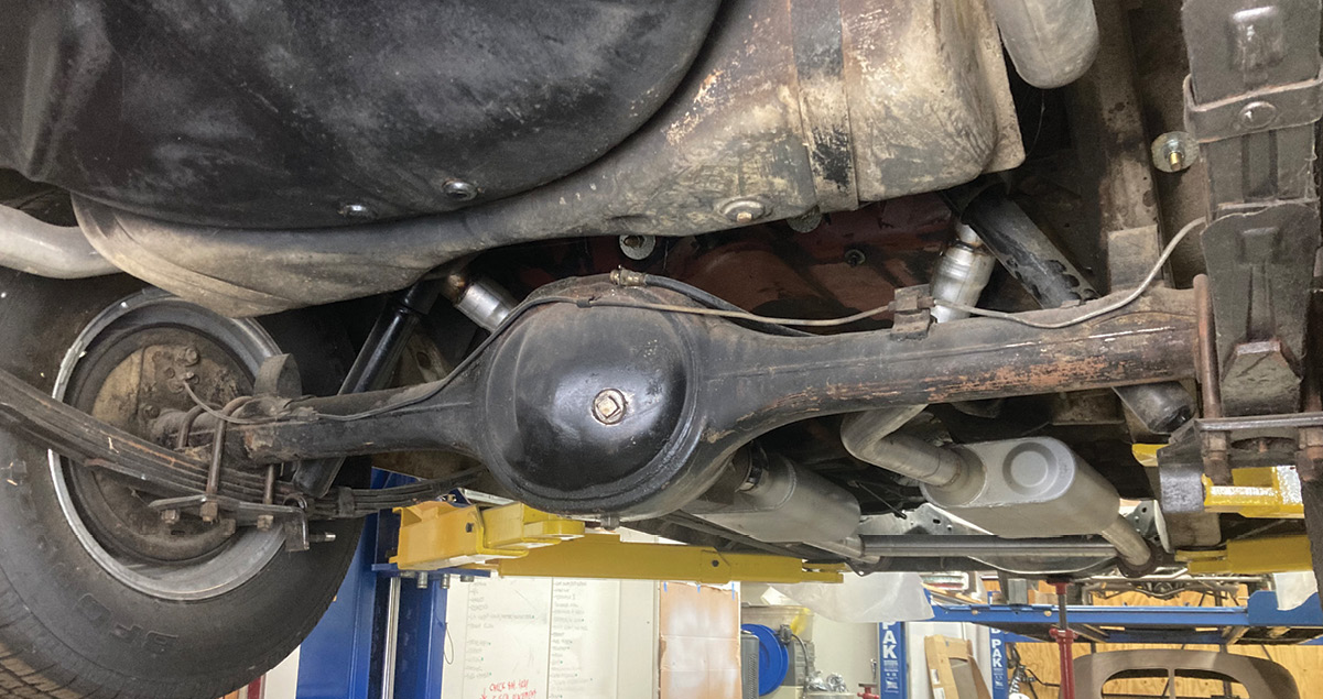
Given the specs of our LS3 engine package, it was obvious that an upgrade in the rearend might be appropriate, since it was one item that hadn’t been touched since the wagon was new, aside from the regular fluid changes and brake jobs. The rather anemic rear served its dutiful purpose all these years, but with an expected 400-plus horsepower, it’s time for a stouter platform.
1. Given the specs of our LS3 engine package, it was obvious that an upgrade in the rearend might be appropriate, since it was one item that hadn’t been touched since the wagon was new, aside from the regular fluid changes and brake jobs. The rather anemic rear served its dutiful purpose all these years, but with an expected 400-plus horsepower, it’s time for a stouter platform.
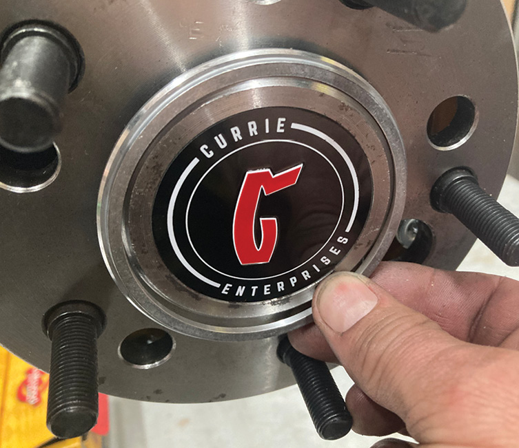
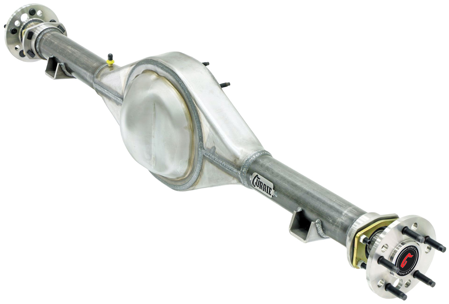
The backbone to our rearend build is this Currie 9-inch Ford housing and axle package from Summit Racing (PN- CUR-CE-GMB5557X). Built to stock axle width dimensions, the housing also features stock suspension spring pad mounting locations and original wheel bolt patterns for a true, drop-in installation. Billet housing ends utilize late-model Ford Torino large bearings while 31-spline 1541 alloy axles make for a bulletproof package.
2. The backbone to our rearend build is this Currie 9-inch Ford housing and axle package from Summit Racing (PN- CUR-CE-GMB5557X). Built to stock axle width dimensions, the housing also features stock suspension spring pad mounting locations and original wheel bolt patterns for a true, drop-in installation. Billet housing ends utilize late-model Ford Torino large bearings while 31-spline 1541 alloy axles make for a bulletproof package.
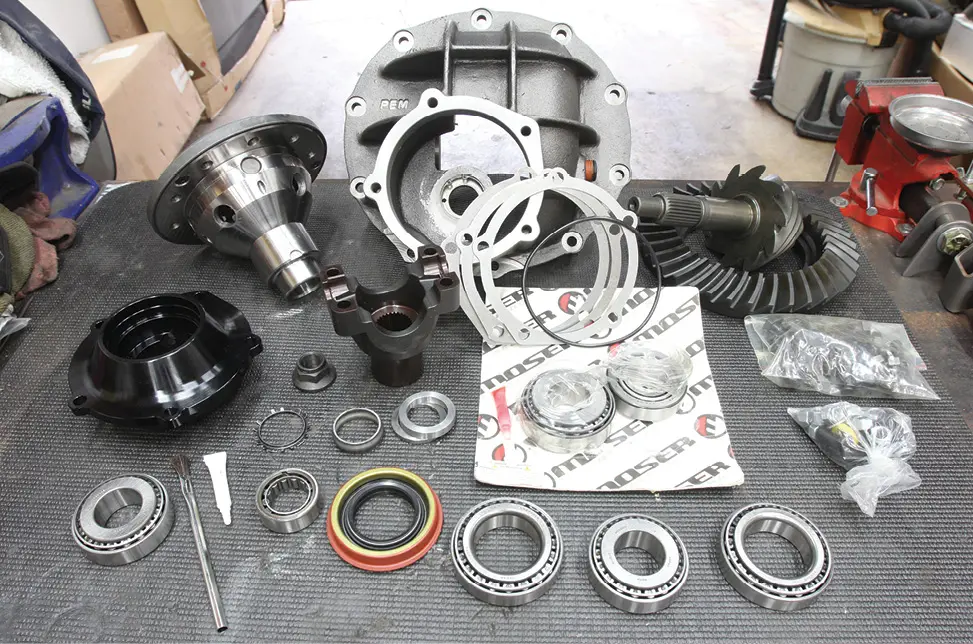
Our 9-inch housing will be stuffed with a myriad of components, including a nodular iron Third Member case, Trac-Loc limited-slip differential, 3.70 ring-and-pinion, upgraded Daytona pinion support, and all the necessary shims, seals, and bearings.
3. Our 9-inch housing will be stuffed with a myriad of components, including a nodular iron Third Member case, Trac-Loc limited-slip differential, 3.70 ring-and-pinion, upgraded Daytona pinion support, and all the necessary shims, seals, and bearings.
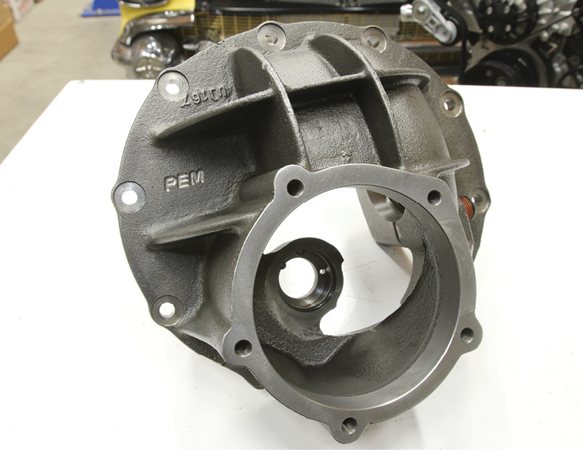
First up, we’ll be assembling the third member into this Summit Racing nodular iron case (PN- SUM-CTDHNI3062). These housings are quality-built at a budget price and feature forged steel caps and 1/2- to 13-inch Grade 8 cap bolts. From this point forward, it should be noted that all parts have been thoroughly cleaned before assembly begins.
4. First up, we’ll be assembling the third member into this Summit Racing nodular iron case (PN- SUM-CTDHNI3062). These housings are quality-built at a budget price and feature forged steel caps and 1/2- to 13-inch Grade 8 cap bolts. From this point forward, it should be noted that all parts have been thoroughly cleaned before assembly begins.
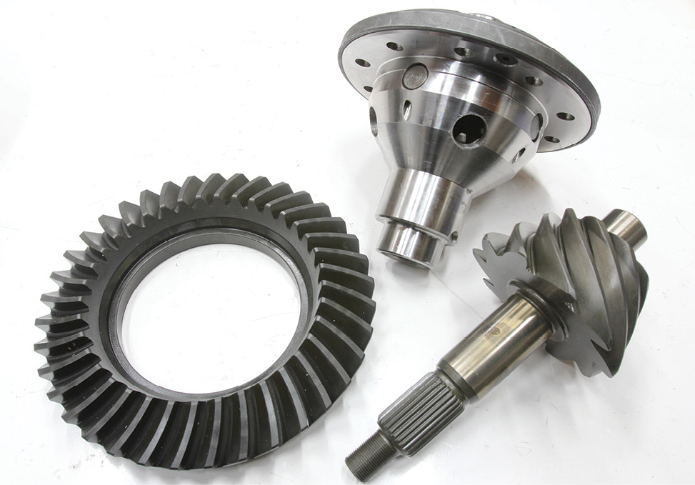
A Summit Racing Trac-Loc Differential (PN- SUM-CTF9TRACL31) will be used to ensure both tires put the power to the pavement evenly while a similarly branded 3.70:1 ring-and-pinion set (PN- SUM-740910) will keep the tires spinning at a manageable rpm.
5. A Summit Racing Trac-Loc Differential (PN- SUM-CTF9TRACL31) will be used to ensure both tires put the power to the pavement evenly while a similarly branded 3.70:1 ring-and-pinion set (PN- SUM-740910) will keep the tires spinning at a manageable rpm.
Assembly begins by pressing the differential bearings in place. Anytime a bearing is pressed into service, care must be made to ensure that the inner surface of the bearing is used as the driven surface and not the bearing cage itself.
6. Assembly begins by pressing the differential bearings in place. Anytime a bearing is pressed into service, care must be made to ensure that the inner surface of the bearing is used as the driven surface and not the bearing cage itself.
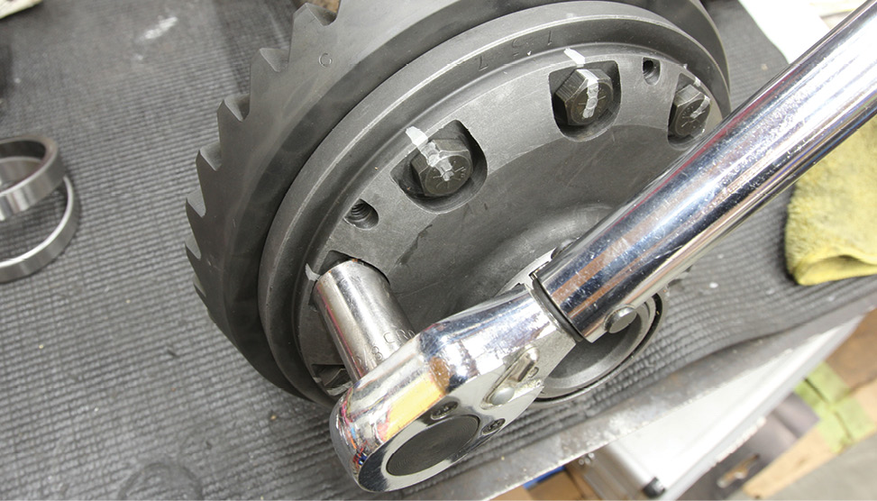
Next, the ring gear is installed using the provided hardware, each receiving a dab of threadlocker. Note the axle on the ring gear side of the diff that has been temporarily installed to help hold the diff while the ring gear bolts are torqued to 65 lb-ft in subsequent stages. The ring gear bolts are marked after being torqued to spec to ensure nothing is overlooked.
7. Next, the ring gear is installed using the provided hardware, each receiving a dab of threadlocker. Note the axle on the ring gear side of the diff that has been temporarily installed to help hold the diff while the ring gear bolts are torqued to 65 lb-ft in subsequent stages. The ring gear bolts are marked after being torqued to spec to ensure nothing is overlooked.
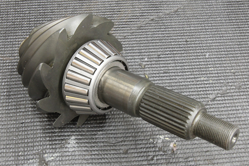
The pinion bearing is pressed onto the pinion in a similar fashion. The 9-inch features a removable pinion cartridge, allowing the user to adjust the pinion mounting depth independent of bearing preload.
8. The pinion bearing is pressed onto the pinion in a similar fashion. The 9-inch features a removable pinion cartridge, allowing the user to adjust the pinion mounting depth independent of bearing preload.
To ensure proper bearing preload, two methods can be used to properly space the pinion gear in the pinion cartridge: a solid spacer or a crush sleeve. While the crush sleeve is a “set it and forget it” design, it cannot be reused. Each time the pinion is removed from the cartridge, a new sleeve is required. Alternatively, once proper preload is determined using the solid spacer arrangement, the assembly can be disassembled and reassembled at nauseum. Pictured here are the crush sleeve and solid spacer along with a selection of shims.
9. To ensure proper bearing preload, two methods can be used to properly space the pinion gear in the pinion cartridge: a solid spacer or a crush sleeve. While the crush sleeve is a “set it and forget it” design, it cannot be reused. Each time the pinion is removed from the cartridge, a new sleeve is required. Alternatively, once proper preload is determined using the solid spacer arrangement, the assembly can be disassembled and reassembled at nauseum. Pictured here are the crush sleeve and solid spacer along with a selection of shims.
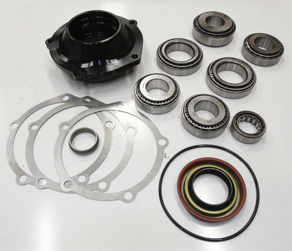
We opted to go with the upgraded Summit Racing Daytona Pinion Support (PN- SUM-730919) to take advantage of the larger pinion support bearing and superior design of the support itself. A Daytona bearing kit (PN- MSR-PB028) in addition to a Summit Racing Ring and Pinion Installation Kit (PN- SUM-G7915K) gets us all we need to complete the installation of the pinion assembly.
10. We opted to go with the upgraded Summit Racing Daytona Pinion Support (PN- SUM-730919) to take advantage of the larger pinion support bearing and superior design of the support itself. A Daytona bearing kit (PN- MSR-PB028) in addition to a Summit Racing Ring and Pinion Installation Kit (PN- SUM-G7915K) gets us all we need to complete the installation of the pinion assembly.
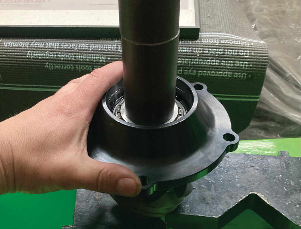
Assembly of the pinion support starts with the installation of the pinion support bearing races pressed in place. The pinion support is then placed over the pinion gear, the tail bearing installed, and the assembly pressed together with slight pressure to ensure everything seats properly.
11. Assembly of the pinion support starts with the installation of the pinion support bearing races pressed in place. The pinion support is then placed over the pinion gear, the tail bearing installed, and the assembly pressed together with slight pressure to ensure everything seats properly.
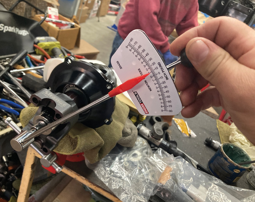
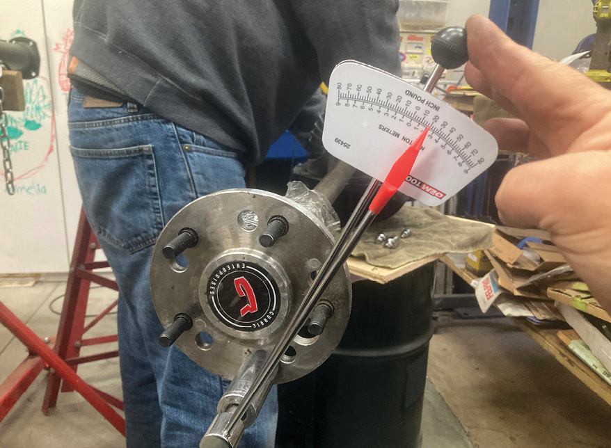
A Strange Engineering 1350-style Forged Steel yoke (PN- STR-U1603) is now installed, along with a pinion yoke spacer kit (PN- STR-N-1918) and an old pinion nut (used for setup only), torqued to 125 lb-ft. Next, we test the torque of the pinion assembly using a torque-to-turn wrench. We’re looking for a range of 13 to 15 in-lb for new bearings. At this rate, the torque-to-turn rating is just under 10 in-lb, so we’ll be removing a shim, pressing the assembly back together, and measuring the torque-to-turn again until we’re within range. We’re going to wait to install the pinion yoke seal, as the preload needs to be set without the seal installed since the seal rubbing on the surface of the driven assembly can provide a false torque-to-turn reading. We’ll install the seal a little later in the process.
12. A Strange Engineering 1350-style Forged Steel yoke (PN- STR-U1603) is now installed, along with a pinion yoke spacer kit (PN- STR-N-1918) and an old pinion nut (used for setup only), torqued to 125 lb-ft. Next, we test the torque of the pinion assembly using a torque-to-turn wrench. We’re looking for a range of 13 to 15 in-lb for new bearings. At this rate, the torque-to-turn rating is just under 10 in-lb, so we’ll be removing a shim, pressing the assembly back together, and measuring the torque-to-turn again until we’re within range. We’re going to wait to install the pinion yoke seal, as the preload needs to be set without the seal installed since the seal rubbing on the surface of the driven assembly can provide a false torque-to-turn reading. We’ll install the seal a little later in the process.
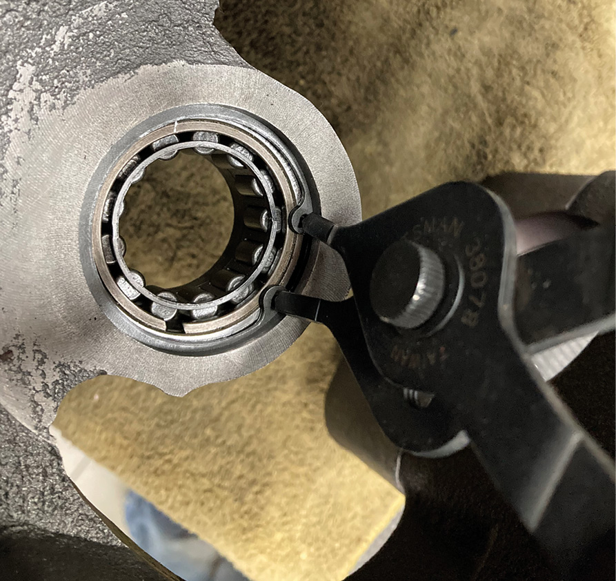
Setting the pinion housing aside for the moment, our attention is turned to the nodular iron third member case, installing the pinion bearing first, held fast by a snap ring.
13. Setting the pinion housing aside for the moment, our attention is turned to the nodular iron third member case, installing the pinion bearing first, held fast by a snap ring.
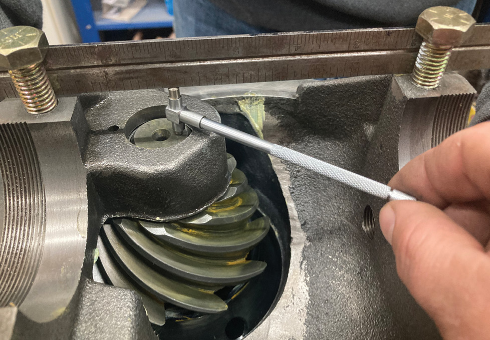
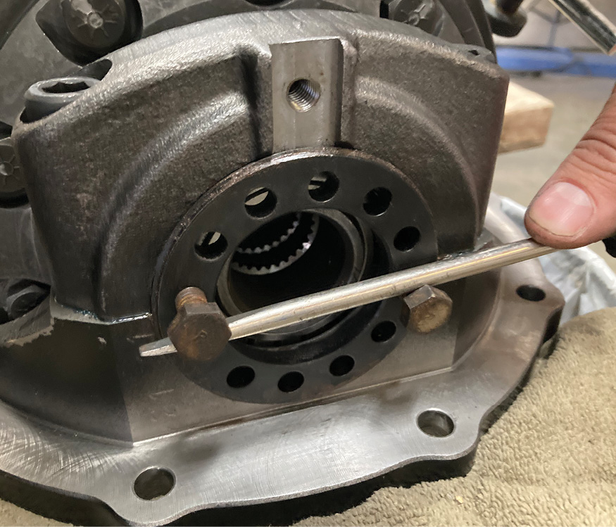
With the pinion bearing in place, the pinion cartridge assembly can be installed into the third member case. Ring-and-pinion gears are sold as a matched set, usually with a clearance number etched into the nose of the pinion gear. This is the distance from the centerline of the ring gear to the nose of the pinion gear shaft, when set up at the factory. For our pinion gear, it’s marked 1.031 inches. A quick measurement gives us an initial installed depth of 1.017 inches with no shims installed between the pinion cartridge assembly and the third member case. Note that the top of the cap surface is in line with the center of the ring gear, so a straightedge across this surface, held by a pair of temporary cap bolts, gives us a good point of reference to measure against it and the nose of the pinion gear.
14. With the pinion bearing in place, the pinion cartridge assembly can be installed into the third member case. Ring-and-pinion gears are sold as a matched set, usually with a clearance number etched into the nose of the pinion gear. This is the distance from the centerline of the ring gear to the nose of the pinion gear shaft, when set up at the factory. For our pinion gear, it’s marked 1.031 inches. A quick measurement gives us an initial installed depth of 1.017 inches with no shims installed between the pinion cartridge assembly and the third member case. Note that the top of the cap surface is in line with the center of the ring gear, so a straightedge across this surface, held by a pair of temporary cap bolts, gives us a good point of reference to measure against it and the nose of the pinion gear.
This results in a difference of 0.014 inch, our baseline shim pack. The pinion cartridge is then torqued to 35 lb-ft without the O-ring installed, which we’ll slip in a little later once the backlash is finalized.
15. This results in a difference of 0.014 inch, our baseline shim pack. The pinion cartridge is then torqued to 35 lb-ft without the O-ring installed, which we’ll slip in a little later once the backlash is finalized.
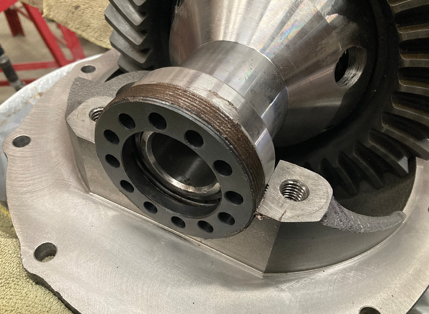
On the opposite side of the diff case, the Trac Loc differential assembly, bearings, and adjuster nuts are set in place. A light coat of gear oil was applied to each bearing prior to assembly. The adjuster nuts should thread in and out smoothly without the caps. If they don’t, they could be cross threaded. Antiseize is applied to the threaded surface to ensure smooth operation. At this point, the adjuster nuts are snugged up against the bearings hand tight.
16. On the opposite side of the diff case, the Trac Loc differential assembly, bearings, and adjuster nuts are set in place. A light coat of gear oil was applied to each bearing prior to assembly. The adjuster nuts should thread in and out smoothly without the caps. If they don’t, they could be cross threaded. Antiseize is applied to the threaded surface to ensure smooth operation. At this point, the adjuster nuts are snugged up against the bearings hand tight.
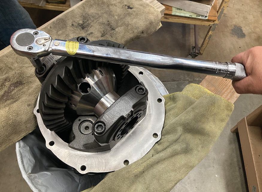
The bearing caps are installed next, with a dab of thread locker on each bolt, torqued to 80 lb-ft.
17. The bearing caps are installed next, with a dab of thread locker on each bolt, torqued to 80 lb-ft.
With the third member in place and the adjuster nuts snug, we’re going to check the bearing preload. For new bearings, we’re looking for around 20 lb-in. An axle inserted into the diff and a torque wrench rotating it yields the torque-to-turn rating, just like when we set the pinion assembly. One of the bearing retainers is tightened until we achieve the noted torque reading, effectively preloading our differential bearings.
18. With the third member in place and the adjuster nuts snug, we’re going to check the bearing preload. For new bearings, we’re looking for around 20 lb-in. An axle inserted into the diff and a torque wrench rotating it yields the torque-to-turn rating, just like when we set the pinion assembly. One of the bearing retainers is tightened until we achieve the noted torque reading, effectively preloading our differential bearings.
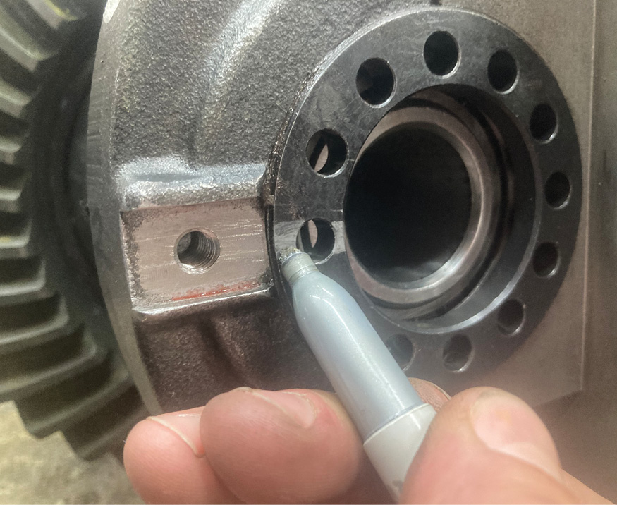
Proper preload is essential on any bearing, so this step is important to ensure longevity of our rearend’s internal components, but we still need to adjust the backlash between the ring-and-pinion using the adjuster nuts. To maintain the predetermined preload setting, each adjuster nut is marked so that when the ring gear is adjusted, the nuts are rotated evenly. One turn in on one side, one turn out on the other, for example.
19. Proper preload is essential on any bearing, so this step is important to ensure longevity of our rearend’s internal components, but we still need to adjust the backlash between the ring-and-pinion using the adjuster nuts. To maintain the predetermined preload setting, each adjuster nut is marked so that when the ring gear is adjusted, the nuts are rotated evenly. One turn in on one side, one turn out on the other, for example.
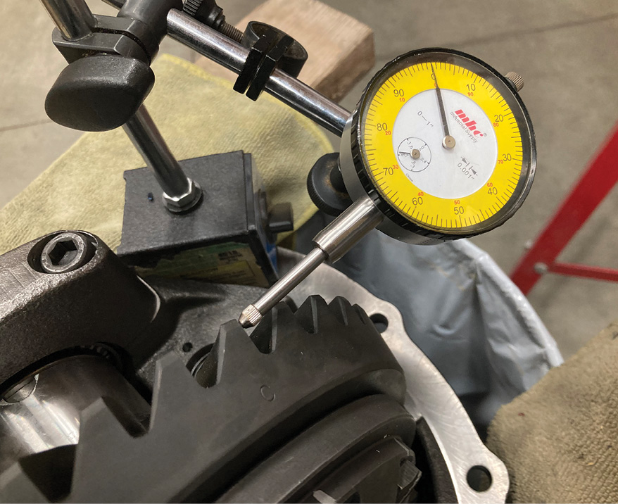
Setting the backlash is accomplished by moving the ring gear side to side in the diff case via the adjuster nuts, bringing it closer to or further from the pinion gear. To measure this, a dial indicator mounted on a stand attached to the diff case is zero’d out at the top of one of the ring gear’s teeth and the ring gear rocked back and forth. Our initial reading shows that our lash is 0.012 inch. Spec for a new gearset calls for 0.007 to 0.010 inch, so we’re a little loose.
20. Setting the backlash is accomplished by moving the ring gear side to side in the diff case via the adjuster nuts, bringing it closer to or further from the pinion gear. To measure this, a dial indicator mounted on a stand attached to the diff case is zero’d out at the top of one of the ring gear’s teeth and the ring gear rocked back and forth. Our initial reading shows that our lash is 0.012 inch. Spec for a new gearset calls for 0.007 to 0.010 inch, so we’re a little loose.
Using the adjuster nuts, we rotate each side an equal amount, careful to maintain the preload setting while bringing the ring gear ever so slightly closer to the pinion gear. Another reading of the dial indicator yields 0.007-inch backlash, right on the money, but we can’t get excited yet.
21. Using the adjuster nuts, we rotate each side an equal amount, careful to maintain the preload setting while bringing the ring gear ever so slightly closer to the pinion gear. Another reading of the dial indicator yields 0.007-inch backlash, right on the money, but we can’t get excited yet.
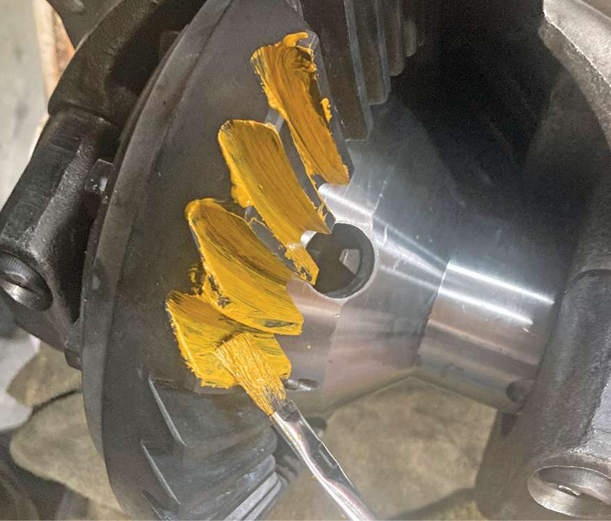
Checking the contact pattern between the ring-and-pinion is a tedious, but an important step. With a little patience, a perfect pattern can be achieved. With marking compound on both the coast and driver side of a couple ring gear teeth, the assembly is rotated until the two gears mesh in the marked area. A couple back and forth rotations is all it takes for a decent reading.
22. Checking the contact pattern between the ring-and-pinion is a tedious, but an important step. With a little patience, a perfect pattern can be achieved. With marking compound on both the coast and driver side of a couple ring gear teeth, the assembly is rotated until the two gears mesh in the marked area. A couple back and forth rotations is all it takes for a decent reading.
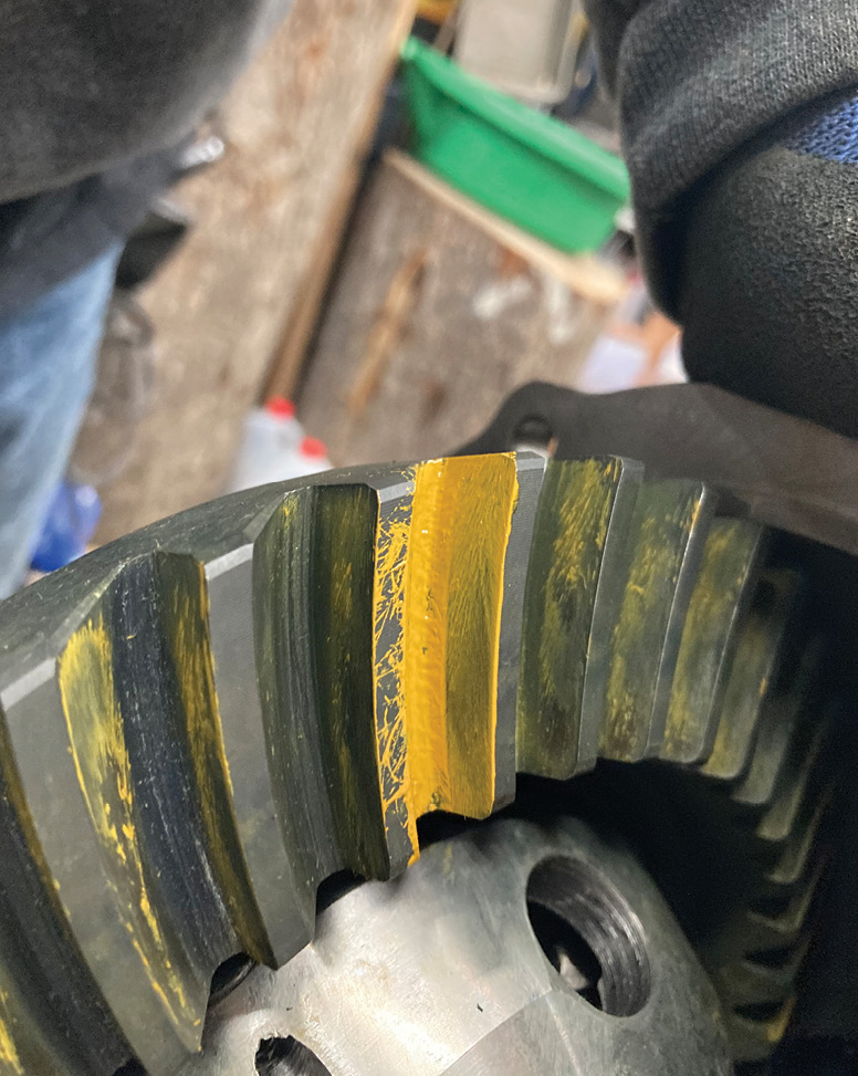
Reading the contact pattern can be a bit of a challenge depending upon how well the pattern is made. Here, you can see that the driver side of the tooth pattern is on the center of the tooth, with a slight favor toward the toe. This is a pretty good reading.
23. Reading the contact pattern can be a bit of a challenge depending upon how well the pattern is made. Here, you can see that the driver side of the tooth pattern is on the center of the tooth, with a slight favor toward the toe. This is a pretty good reading.
Looking at the coast side it too is centered but favors the heel of the tooth slightly. An increase in the pinion-mounted distance (a decrease in pinion shim thickness) would bring the pattern toward the toe (bottom) side of the tooth but will also move it toward the top as well. This will also move the pattern on the driver side toward the heel and top, however, something that we’d like to avoid as that pattern looks pretty good. A pattern that runs off the heel or toe side of the tooth or runs off the top or deep into the root side is bad news, so keeping it centered is the key. It should be noted that if the pattern is unacceptable and the pinion shims changed, the backlash needs to be checked and set again as the relationship between the ring-and-pinion may have changed. Sometimes, it’s as simple as slightly increasing or decreasing the backlash to get the pattern correct.
24. Looking at the coast side it too is centered but favors the heel of the tooth slightly. An increase in the pinion-mounted distance (a decrease in pinion shim thickness) would bring the pattern toward the toe (bottom) side of the tooth but will also move it toward the top as well. This will also move the pattern on the driver side toward the heel and top, however, something that we’d like to avoid as that pattern looks pretty good. A pattern that runs off the heel or toe side of the tooth or runs off the top or deep into the root side is bad news, so keeping it centered is the key. It should be noted that if the pattern is unacceptable and the pinion shims changed, the backlash needs to be checked and set again as the relationship between the ring-and-pinion may have changed. Sometimes, it’s as simple as slightly increasing or decreasing the backlash to get the pattern correct.
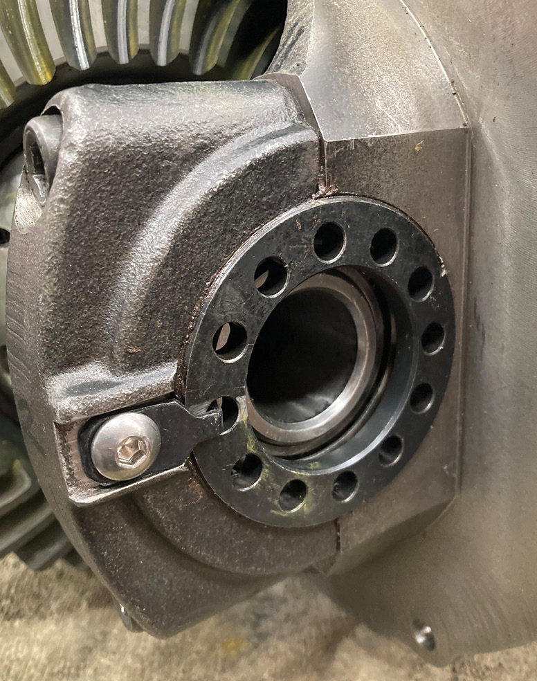
Once the backlash, preload, and contact pattern are good to go, the adjuster nut retainer clips are installed and the fasteners torqued to 20 lb-ft with a dab of thread locker for good measure.
25. Once the backlash, preload, and contact pattern are good to go, the adjuster nut retainer clips are installed and the fasteners torqued to 20 lb-ft with a dab of thread locker for good measure.
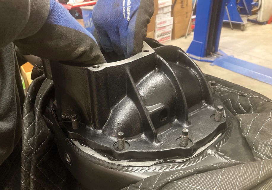
Initial assembly of the differential case is complete and our attention is turned to the rearend housing. First, the housing is thoroughly cleaned inside and out. Before a bead of RTV is applied to the gasket surface, a gasket is then installed on the housing, followed by another bead of RTV on the diff case side of said gasket before the diff case assembly is installed. Note that we’ve removed the pinion assembly to ease installation.
26. Initial assembly of the differential case is complete and our attention is turned to the rearend housing. First, the housing is thoroughly cleaned inside and out. Before a bead of RTV is applied to the gasket surface, a gasket is then installed on the housing, followed by another bead of RTV on the diff case side of said gasket before the diff case assembly is installed. Note that we’ve removed the pinion assembly to ease installation.
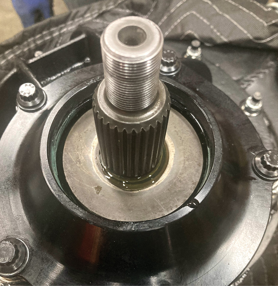
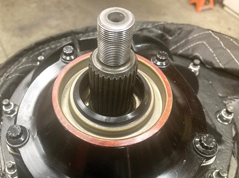
A liberal amount of gear oil is applied to the ring gear and diff before the pinion assembly is dropped in place for the final time with a lubricated O-ring seal in place. The bolts receive a dab of thread locker before being torqued to 35 lb-ft. Before the pinion seal is installed, a splash washer is set in place. This helps the seal do its job by preventing high-pressure gear oil from blasting out of the bearing directly against the back side of the seal, potentially causing it to fail and leak.
27. A liberal amount of gear oil is applied to the ring gear and diff before the pinion assembly is dropped in place for the final time with a lubricated O-ring seal in place. The bolts receive a dab of thread locker before being torqued to 35 lb-ft. Before the pinion seal is installed, a splash washer is set in place. This helps the seal do its job by preventing high-pressure gear oil from blasting out of the bearing directly against the back side of the seal, potentially causing it to fail and leak.
The seal is now installed followed by the pinion and a new pinion nut (PN- STR-N-1922-A) torqued to 125 lb-ft.
28. The seal is now installed followed by the pinion and a new pinion nut (PN- STR-N-1922-A) torqued to 125 lb-ft.
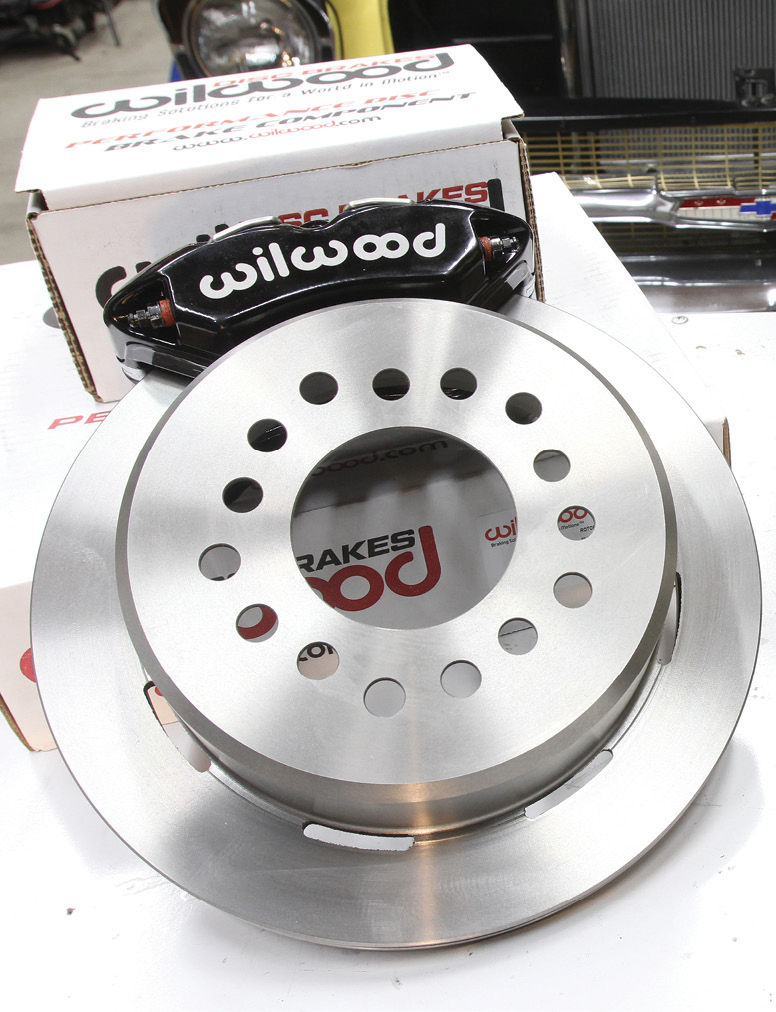
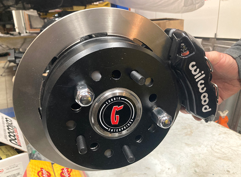
To complement the front brakes we installed in a previous story, a Wilwood DynaPro 11-inch disc brake kit (PN- 140-11389) will be used.
29. To complement the front brakes we installed in a previous story, a Wilwood DynaPro 11-inch disc brake kit (PN- 140-11389) will be used.
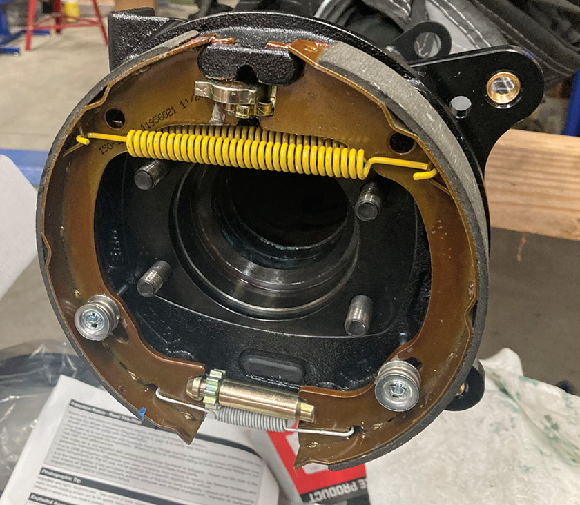
Wilwood’s DynaPro kit features a low-profile rear parking brake kit with an integrated caliper mounting bracket that is installed before the axle and is retained using a special Wilwood axle bearing retainer plate after the axle is installed.
30. Wilwood’s DynaPro kit features a low-profile rear parking brake kit with an integrated caliper mounting bracket that is installed before the axle and is retained using a special Wilwood axle bearing retainer plate after the axle is installed.
Wilwood prefers to mount their rotors in a more accurate hub register-centric manner, as opposed to relying on the wheel studs to properly align the rotor. Due to this, a rotor registration adapter is included in the kit to align the rotor perfectly to the axle register.
31. Wilwood prefers to mount their rotors in a more accurate hub register-centric manner, as opposed to relying on the wheel studs to properly align the rotor. Due to this, a rotor registration adapter is included in the kit to align the rotor perfectly to the axle register.
A pair of lug nuts holds the rotor temporarily as the four-piston DynaPro caliper is installed using the provided ³/8-inch hardware.
32. A pair of lug nuts holds the rotor temporarily as the four-piston DynaPro caliper is installed using the provided ⅜-inch hardware.
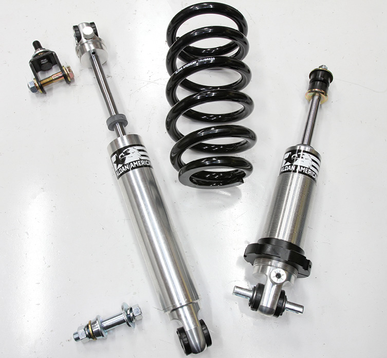
The new rearend will bolt up to a pair of recently replaced leaf springs but will be dampened by a pair of Aldan American single-adjustable shocks (PN 100111) from Summit Racing. These TrueLine shock absorbers are designed for a more consistent, smoother ride, giving some control over the dampening to help dial in the ride—an important feature on a big car like Valley’s wagon.
33. The new rearend will bolt up to a pair of recently replaced leaf springs but will be dampened by a pair of Aldan American single-adjustable shocks (PN 100111) from Summit Racing. These TrueLine shock absorbers are designed for a more consistent, smoother ride, giving some control over the dampening to help dial in the ride—an important feature on a big car like Valley’s wagon.
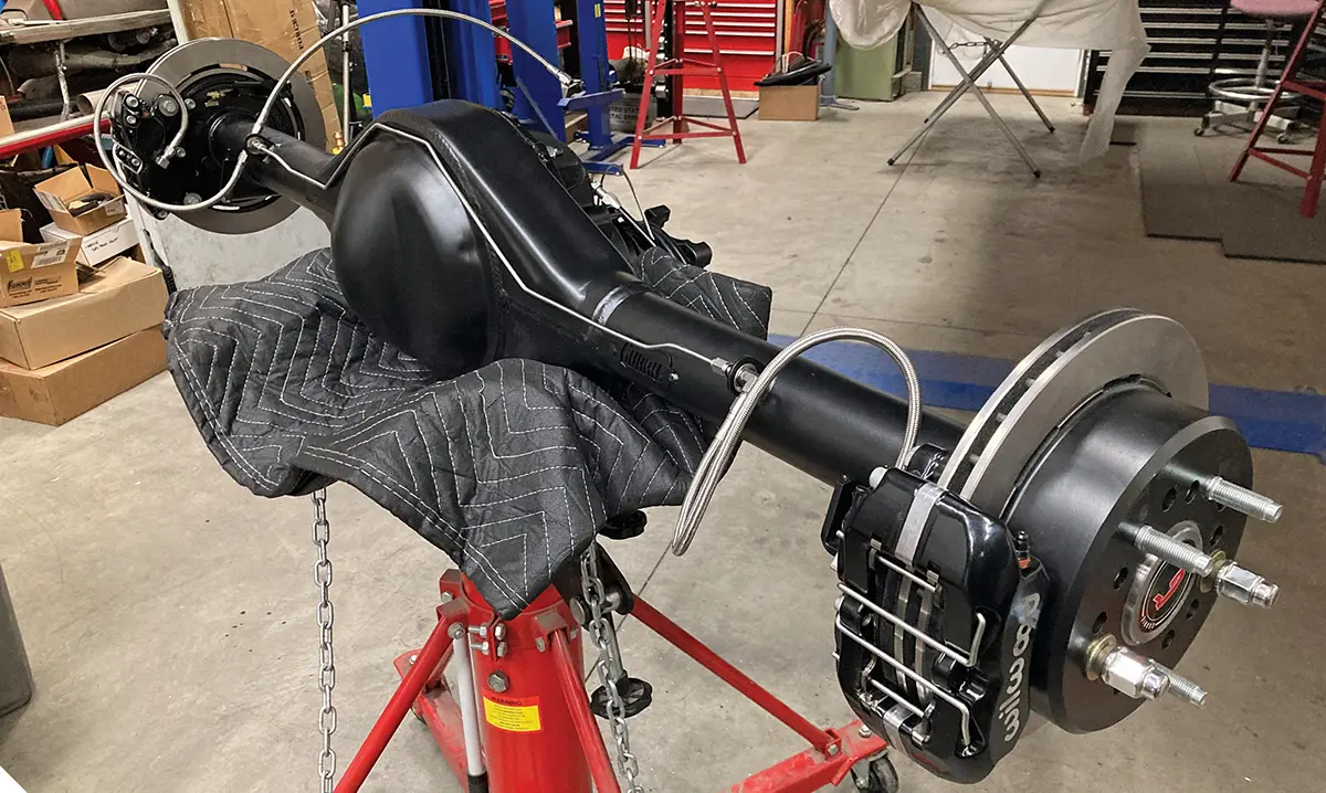
We sent the Currie rearend housing out to get powdercoated before we began the build, and we’re glad we did as it looks great and will continue to do so for years to come. Before we hang the assembled rearend on those Aldan American shocks, we fabricated ³/16-inch stainless steel brake lines and connected hoses to each caliper as well as a hose that will mate the rearend to the frame-mounted line. We’ll cover the brake system plumbing in a future issue, but for now our fully assembled rearend is ready for installation.
34. We sent the Currie rearend housing out to get powdercoated before we began the build, and we’re glad we did as it looks great and will continue to do so for years to come. Before we hang the assembled rearend on those Aldan American shocks, we fabricated ³/16-inch stainless steel brake lines and connected hoses to each caliper as well as a hose that will mate the rearend to the frame-mounted line. We’ll cover the brake system plumbing in a future issue, but for now our fully assembled rearend is ready for installation.
SOURCES
Aldan American
(310) 421-0685
aldanamerican.com
Clampdown Competition
clampdowncomp.com
Summit Racing
(800) 230-3030
summitracing.com
Wilwood Disc Brakes
(805) 388-1188
wilwood.com