

ACP department heading TECH
InTheGarageMedia.com
1966 nova ss drag car yellow hood scoop wheelie bar nhra launch shot
1. Gary Tackett’s 1967 Nova Super Stocker just coming off the line at Pomona—you can see the driver side wheel just about to leave the ground. (Photo Dave Kommel)
Straight Talk on Bumpsteer typography
Three Ways to Ensure Proper Toe
BY Tony ThackerImages BY THE AUTHOR
B

umpsteer is one of those automotive terms that everybody uses but few understand. Luckily for us, our good friend Rick Lefever took on the task of minimizing the bumpsteer in Gary Tackett’s 1967 Nova Super Stock C Modified race car.

Bumpsteer is a situation whereby the car steers itself (even when the steering wheel is not being turned) because incorrect steering geometry causes the toe to change as the wheel goes up and down.

“Gary was experiencing some bumpsteer on the track,” Lefever says, particularly when he came back to earth from a wheelie. Because the toe-in was out, the car was unpredictable.

In the Super Stock class, cars must retain the stock front suspension, including the stock A-arms, however, they can be fitted with rack-and-pinion steering, which was the case in Tackett’s Nova. Like most applications, Tackett’s Nova was fitted with a ’70s Pinto-style rack. The shocks and the upper shock mounts also have to remain in the stock location.

“Locating the rack and setting the steering geometry is something that ideally should be done during the build,” Lefever says. Because the location of the rack is extremely important, however, in this case the car was already built and therefore some compromises had to be made, otherwise we would be into a huge task relocating the rack, and that just wasn’t possible.

“Drag racing exaggerates this situation,” Lefever continues. “Because as the car launches it causes the wheel to travel from stock ride height on the start line to full drop as it lifts the front, to full compression as it returns to earth—all in a matter of seconds. The wheel travels through a large arc and when it comes down it needs to be pointing where you want the car to go.

In the case of Tackett’s Nova, the wheels traveled a total a 3 1/2 inches from top to bottom, and the toe-in varied from 1 inch at the top to 1/8 inch at the bottom—a substantial change of 7/8 inch. Ideally the toe-in should be 1/16 inch either side—1/8-inch total.

In Lefever’s world there are three relatively simple ways to check your toe, and each takes patience as you will invariably have to go back and forth making small adjustments to get it correct. The three methods employ string, a trammel, and a bumpsteer gauge.

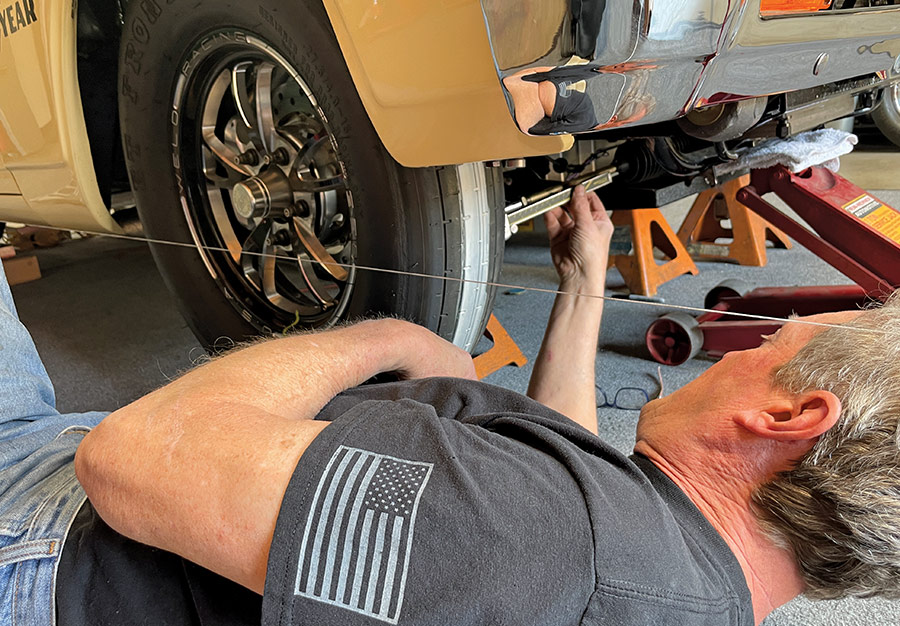
Lefever admits that his string method is somewhat tedious and time-consuming, but in his opinion, and he’s been doing this for 40 years, if you are careful, it’s very accurate, and it’s cheap because you don’t need any special tools or investment—just time and string.

The preparation for measuring and ultimately adjusting toe is the same for all three methods described here.

1966 nova ss drag launch front wheels up yellow paint track prep pass
2. Seconds later and the Nova is in the “up” position. Upon its return to earth, incorrect toe-in, that varied from 1/8 to 1 inch, can cause an unexpected change in direction. (Photo Dave Kommel)
suspension geometry explanation on shop whiteboard with diagrams
3. Rick Lefever explains how the length of the tie rod and its relationship to the A-arms and the rack can cause the toe to change drastically as the wheel arcs through its travel.
weld racing front wheel on longacre digital scale for corner weight
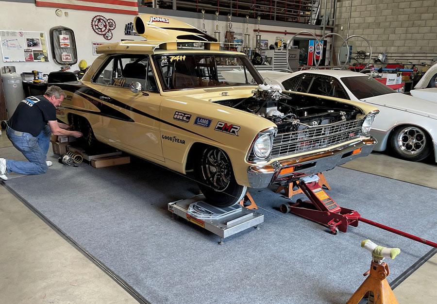
4. Before Lefever tackled the bumpsteer problem, he weighed the car in at 3,200 pounds. Meanwhile, his scales offer a firm support for taking measurements.
front suspension control arm heim joint rack steering detail
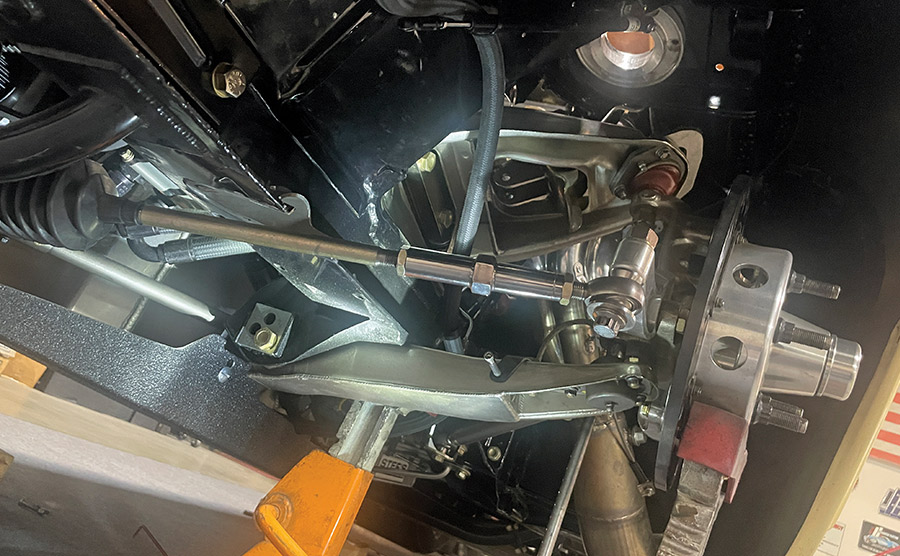
5. Lefever removed the shocks and springs so that he could easily move the wheel up and down through its arc. This is a view of the driver side looking up toward the upper shock mounting.
steering link heim joint close-up with jam nuts and threads
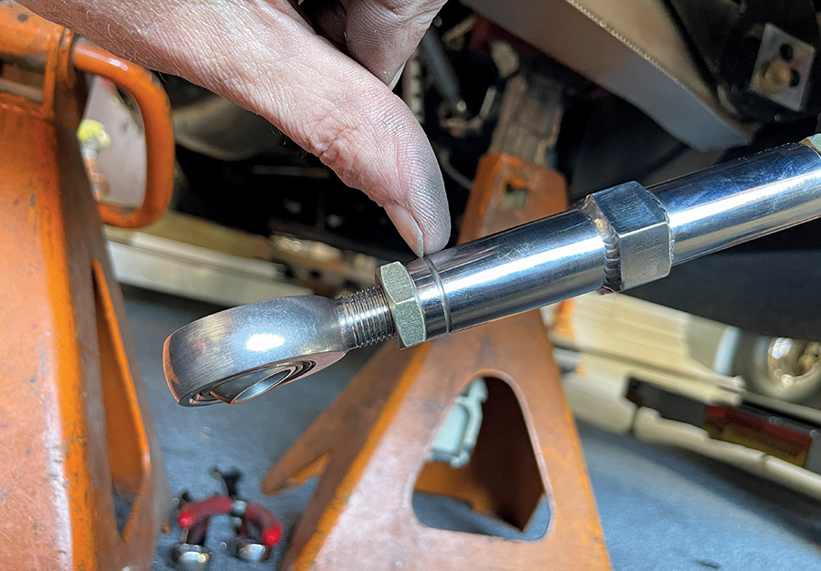
6. One of the first things Lefever did was fabricate left- and right-threaded steel tie-rod adjusters, enabling him to more easily and accurately adjust the toe. Previously, the tie-rod adjusters were both righthand thread and made of aluminum.
front toe alignment string method trackside setup in progress
7. Typically, a lefthand threaded component is identified by a small groove, such as the one Lefever is indicating here at the end of the tie-rod adjuster.
steering shaft detail with grommet pass-through and firewall polish
8. Here, Lefever uses his caliper to measure the thread engagement of the tie rod just to make sure he had enough adjustment before starting the measuring process.
rack and pinion mount and weld bracket details front crossmember
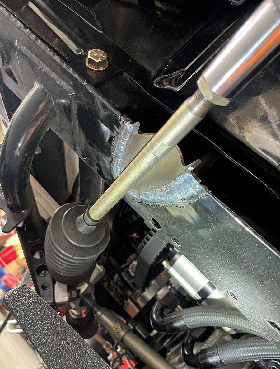
9. Something that Lefever had to do that you probably won’t is re-notch the frame because the cut-out for the tie rod was in the wrong location, enabling the tie rod to hit the frame.
1966 nova toe adjustment string method under front bumper alignment
10. Here you can see where Lefever has moved the notch to align with the travel of the tie rod. It’s attention to detail like this that will ultimately give you a good-handling car.
slotted billet bracket for rack position tuning on 1966 nova drag car
11. Attention to detail are these beautiful polished stainless steel, half-round cups that neatly disguise the notches in the frame for the tie rods.
METHOD 1
measuring toe at front tire using string method 1966 nova setup
12. To begin, Lefever lifts each wheel through its full length of travel from top to bottom (shown). The wheels were found to have 3 1/2 inches of travel and the toe varied from 1 to 1/8 inch at the bottom.
1966 nova drag car on scales during suspension alignment in race shop
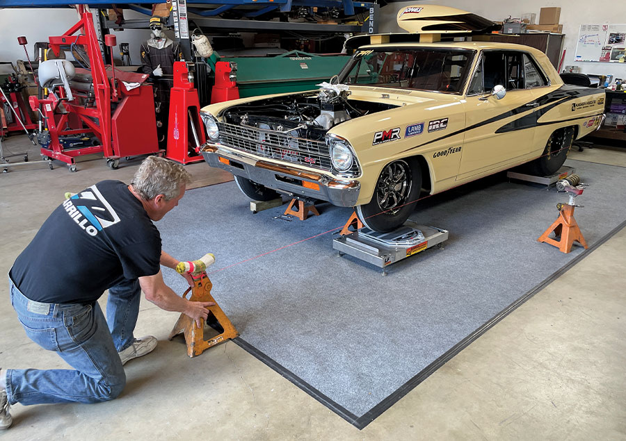
13. Method numero uno is accessible to everybody, as all you need is string, an accurate measuring device (even a good tape measure will work), and two jackstands.
weld racing front wheel on longacre scales for corner weight setup
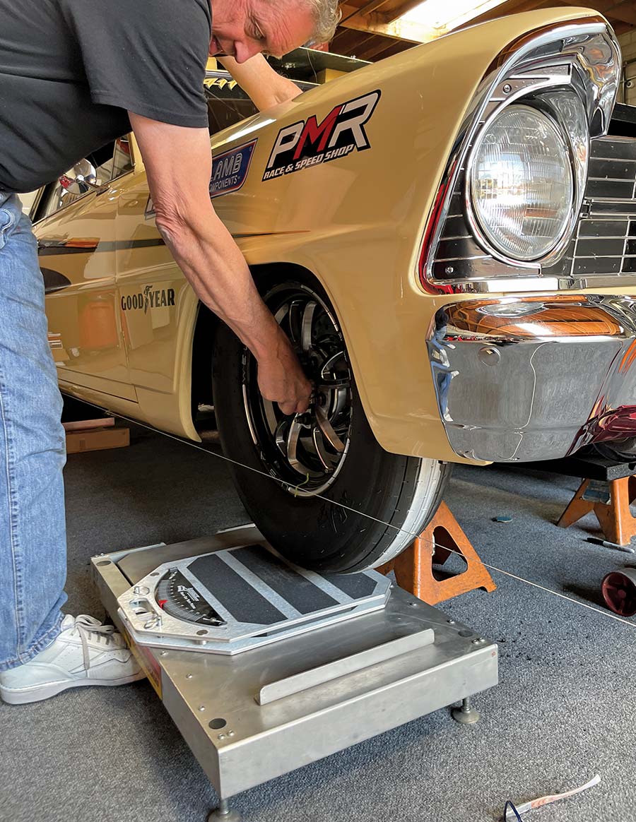
14. Lefever used a small piece of 1/4-inch green masking tape to mark the centerline of the wheel so that as he goes through the measuring process the wheel is always in the same location.
rear slick on longacre scale with alignment string for thrust check
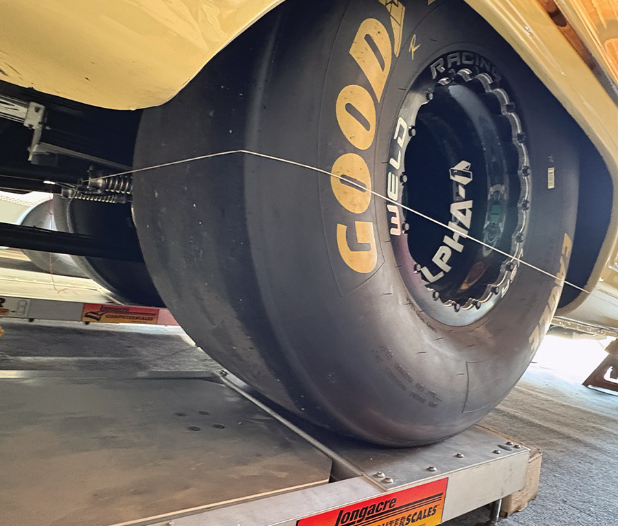
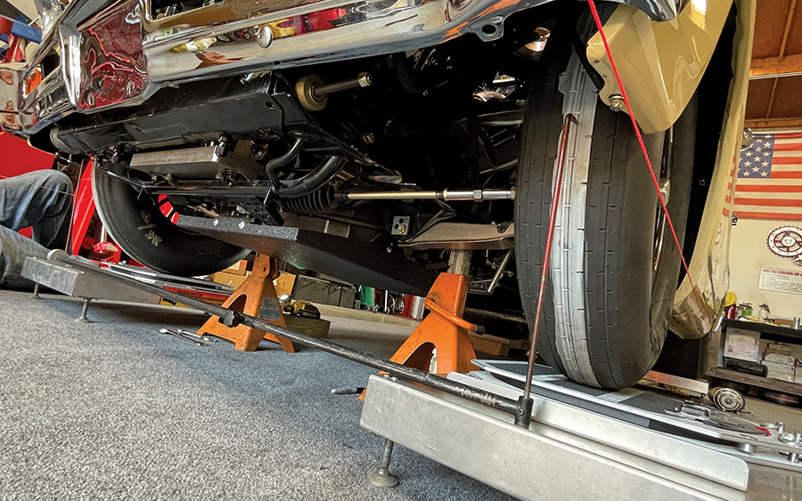
15. The string was wrapped around the rear tires and tightly secured to the ladder bar. The other end of the string is secured to an axle stand placed 5 to 6 feet in front of the car.
laser alignment pointer on weld beadlock during string setup
16. Using a small flashlight, Lefever made sure that the string was exactly parallel to the rear tire. This entails moving the front jackstand left and right until the string is perfectly located.
caliper used to measure toe distance from string to front tire
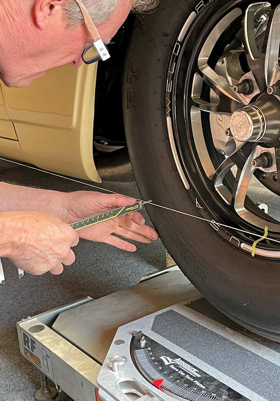
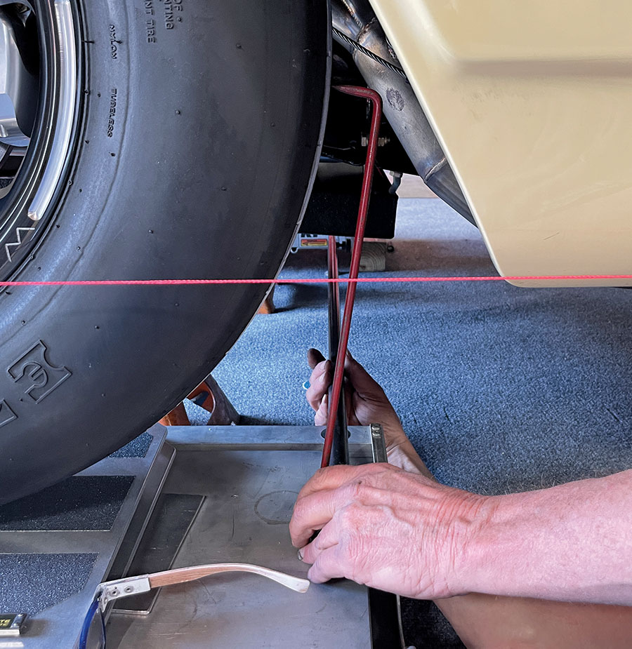
17. Using his Absolute Digimatic digital caliper Lefever measures the distance from the string to the tire at ride height. Care is needed to not move the string, otherwise your measurements will be off.
close-up of toe measurement from string to slick with caliper
18. After measuring the rear of the front tire, another measurement was taken from the front of the front tire. The difference between the front and the rear indicates the toe—in or out.
adjusting tie rod on 1966 nova steering arm during alignment
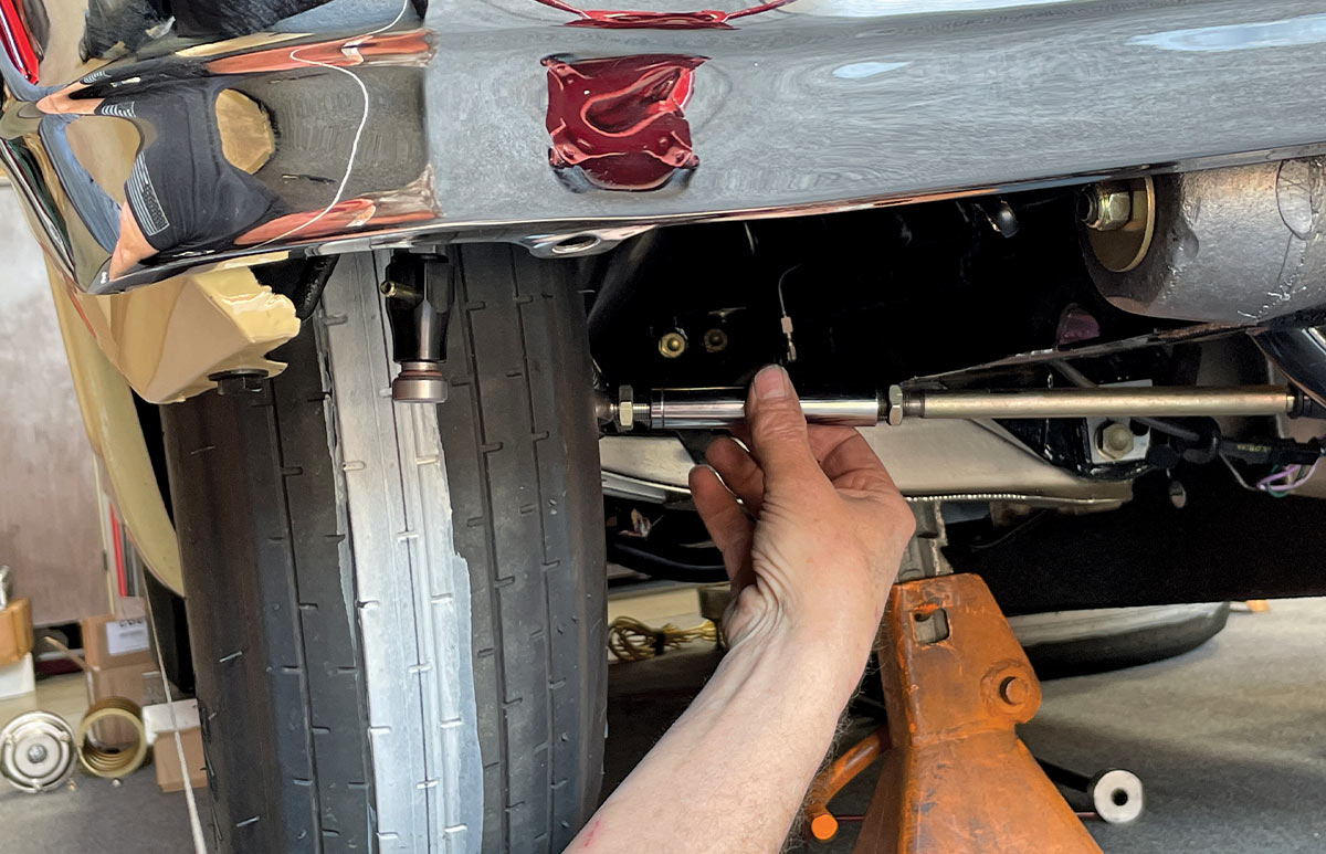
19. Having determined the difference, Lefever twists the tie-rod adjuster to lengthen or shorten the tie rod. In this case, the tie rod was adjusted until the toe was 1/16-inch in.
checking toe on 1966 nova front wheel using string and digital scale
20. Having adjusted the tie rod, Lefever carefully lifted the wheel through its travel arc from bottom to top—a total of 3 1/2 inches. The toe varied from 1 inch at the top to 1/8 inch at the bottom.
measuring toe with string and caliper on 1966 nova front slick
21. The measuring process was repeated at both the rear and the front of the tire with extreme caution as to not move the string causing a distorted measurement.
adjusting heim joint tie rod at steering arm on 1966 nova
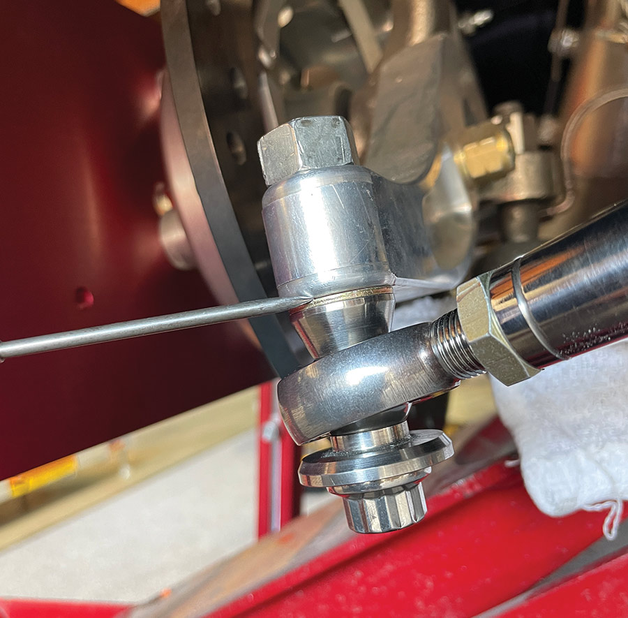
22. To adjust the length or arc of the tie rod, Lefever installs a small washer between the rod end and the steering arm. Once finalized, the washer was replaced with an accurately machined spacer.
close-up of heim joint and laser string on spindle arm
23. A close-up of the washer located between the rod end and the steering arm. A 1/16-inch washer changes the toe by approximately 0.080 inch or 80 thou.
machined tapered bung and cone spacer for tie rod mount
24. Once the correct thickness of the spacer had been determined, Lefever made them out of stainless (left) replacing the aluminum ones. He noted these spacers should be as short as possible. If you have to put more than 1/4-inch spacer between the tie-rod end and the steering arm, then you should move the rack as a long spacer will put too much load on the bolt. This is the reason that this work should be done at the time of the chassis build and not after the car is built.
aligning front thrust line using laser pointer on jack stand
25. Once the passenger side was deemed to be as close as possible given the compromises caused by the location of the rack, Lefever moved to the driver side and repeated the process.
METHOD 2: Trammel
rear axle string bar jig for square alignment setup
26. A trammel is a measuring device consisting of nothing more than a stick or a piece of rigid tube with two adjustable arms, or trammel points, attached to either end. It’s not as simple as string but you might find it easier to use.
checking rear axle square to front tire with magnetic base
27. Lefever began by marking the center of both front tires with white shoe paint and then marking the centerline of each tire with a carefully positioned scribe mounted in a V-block.
1966 nova front suspension visible during alignment with string bar
28. Lefever used his scales as a firm base on which to mount the trammel and then placed the fixed end point on the exact centerline of the tire as seen here on the driver side front tire.
setting rear alignment string height with square behind rear tire
29. After measuring the front, Lefever moved the trammel to the rear of the tires and again measured the distance between the scribed lines. The difference between front and rear is the toe—either in or out.
undercar view of 1966 nova on scales with alignment in progress
30. With the trammel re-positioned back in front of the tires, Lefever was able to determine the toe and adjust accordingly. Like the string method, the trammel method takes time and patience.
adjusting tie rod length for toe alignment on nova front end
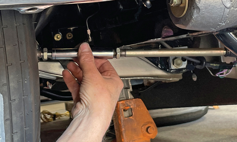
31. Having determined whether the tie rod needed to be lengthened or shortened, Lefever adjusted the length by turning the adjuster out to lengthen or in to shorten.
METHOD 3: Bumpsteer Plates
A large, bright red bump steer gauge tool set up in a garage with a dial indicator on the right side and a vertical ruler
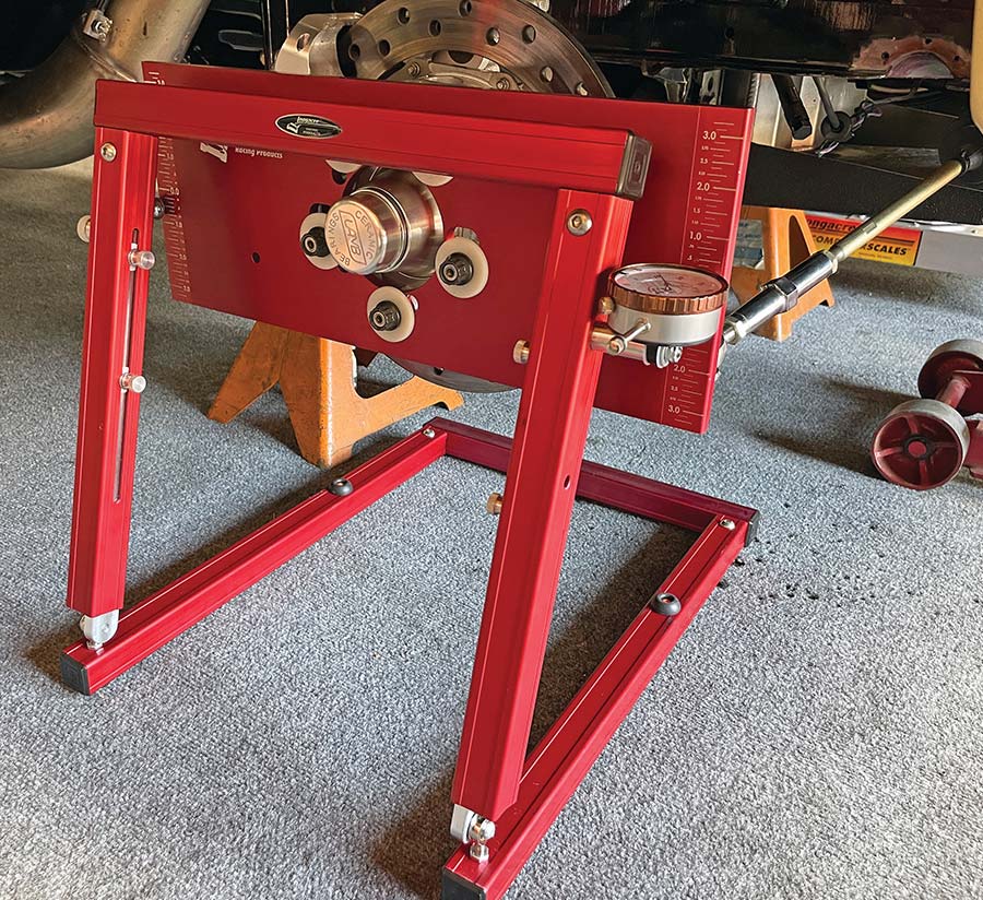
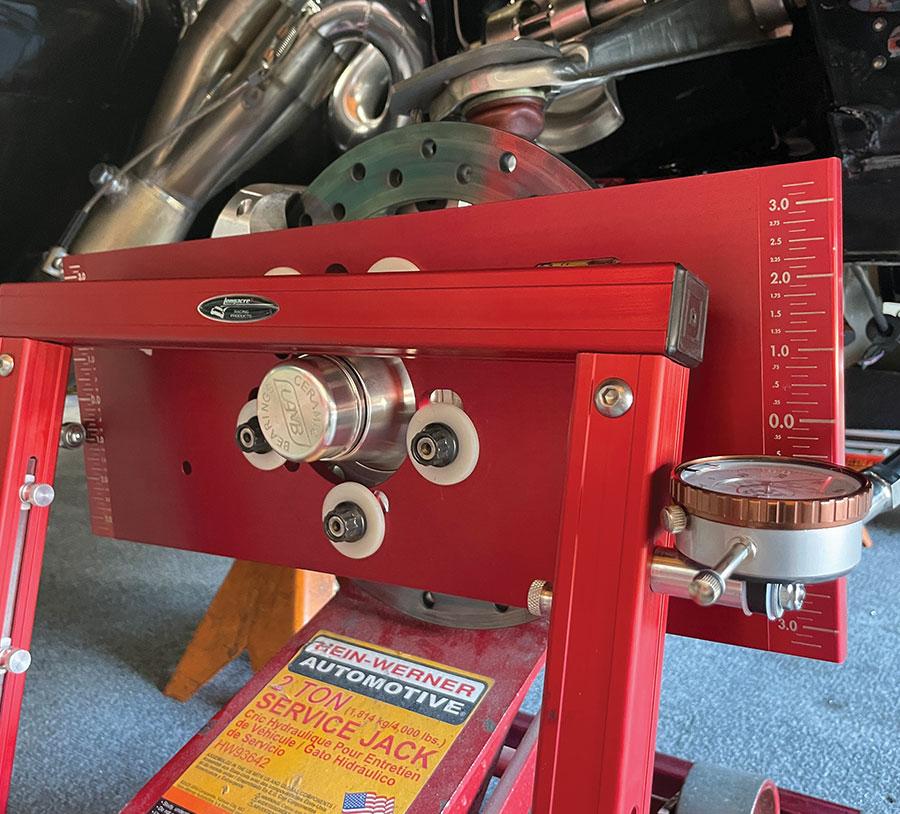
32. There are several companies producing kits for measuring bumpsteer. Lefever decided to try this kit from Longacre Racing products. The kits start at around $300 and go up to $500 for the digital version, which is what Lefever purchased.
attaching Longacre hub plate tool to rotor for castercamber setup
33. To use the Longacre bumpsteer gauge kit, you have to remove the wheels as well as the shocks and springs. The kit comes with this sturdy calibrated 3/8-inch, T6 billet aluminum plate that bolted on using the wheel studs.
a close-up, low-angle shot shows a red hydraulic floor jack holding up the front suspension of a car in a garage
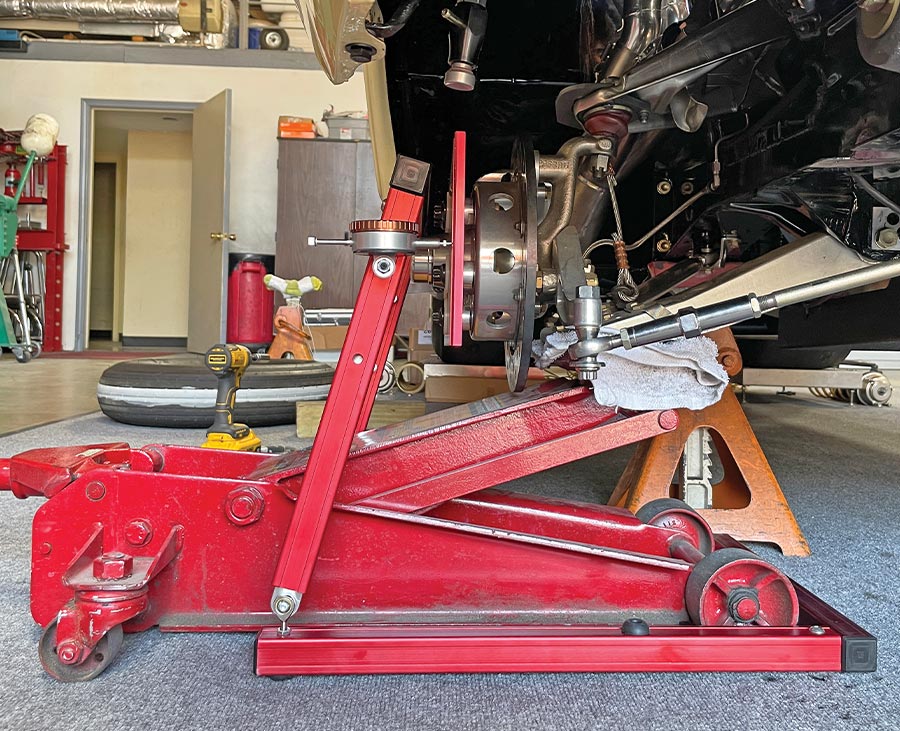
34. The bumpsteer gauge frame was positioned with the U-section under the car so that a floor jack could be installed in order to lift the suspension through its travel.
side view of Longacre castercamber tool aligned with hub
35. Lefever set the car ride height and positioned the frame so that the dial indicator was centralized at the “zero” position on the plate.
measuring camber and caster with gauge and dial indicator tool
36. The suspension was then positioned at the bottom of its travel so that Lefever could measure the toe there.
close-up of a red automotive bump steer gauge tool mounted to the front wheel hub of a race car
37. Finally, using the jack, the suspension was lifted to the top of its travel so that the toe could be measured a third time. Unfortunately, at the top of the travel the spindle was very close to the frame. Nevertheless, Lefever was able to get his measurement.
SOURCE