ACP department heading TECH

InTheGarageMedia.com

Al Scudellari checking pressure gauges while evacuating old A/C system
1. For proper operation, the A/C system must be evacuated with a vacuum pump for 30-45 minutes before charging with refrigerant. To accurately determine if the system is charged properly, Al Scudellari used dedicated gauges to indicate low and high side pressures.
Environmental Impact - Climate Control For '60s Chevys
By Ron Ceridono Photography by Jason Scudellari
T

oday you’d be hard-pressed to find a new car without air conditioning, but in 1962 that wasn’t the case. That year a new Chevy Impala two-door hardtop sport coupe had a factory price of around $2,800, and adding DeLuxe air conditioning bumped the tab by over $360—that’s roughly 13 percent of the base price. As a result, lots of Chevy shoppers back then decided to tough it out and forgo the A/C and cope with hot days by rolling the windows down and turning the windwings out. Of course, all that did was funnel hot air into the passenger compartment, along with the occasional flying insect.

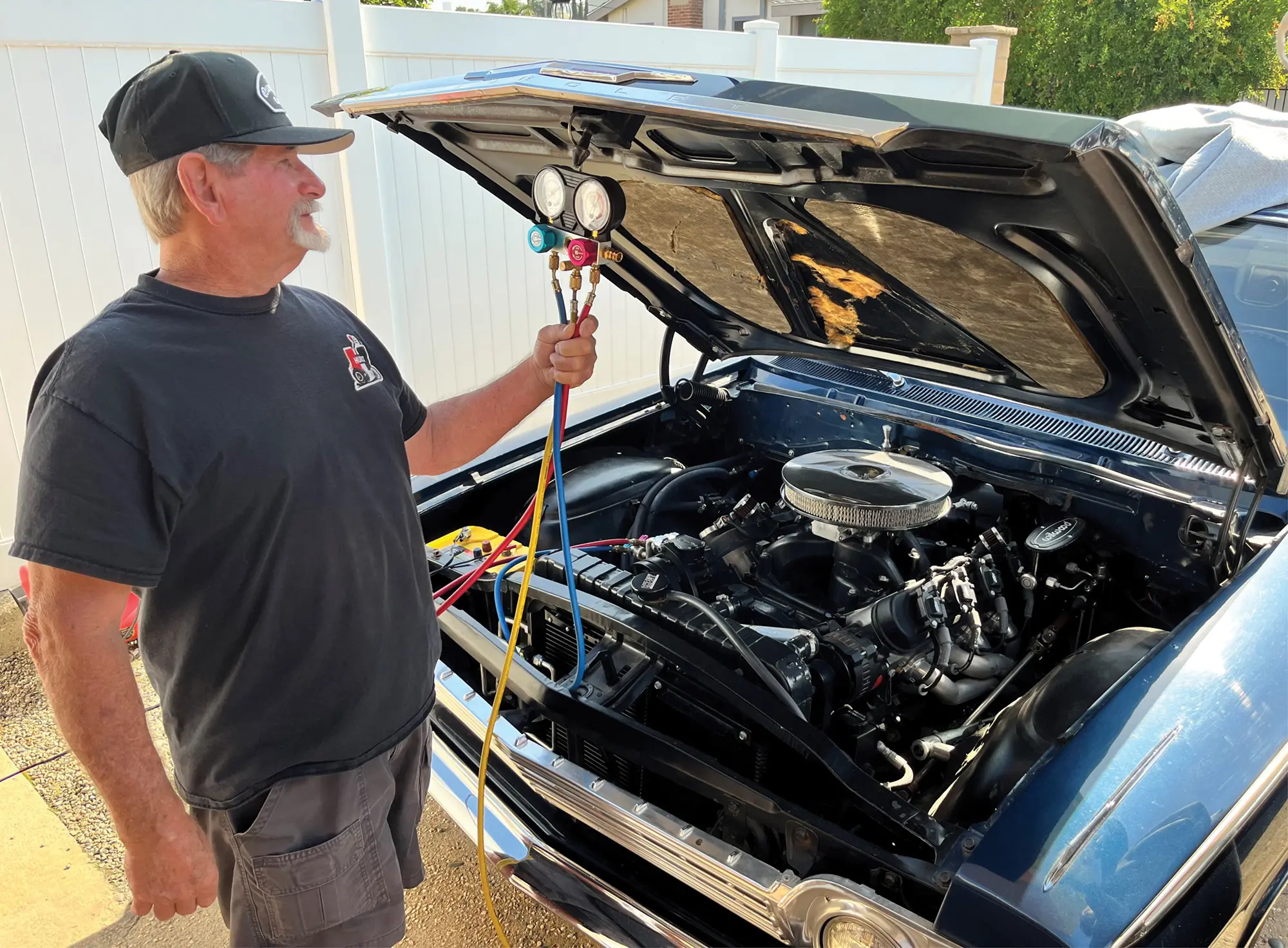
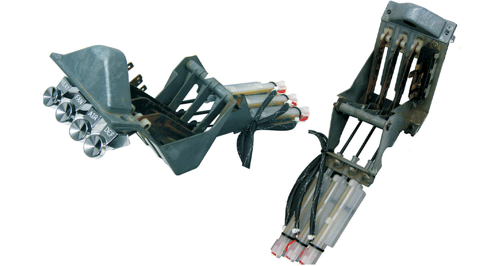
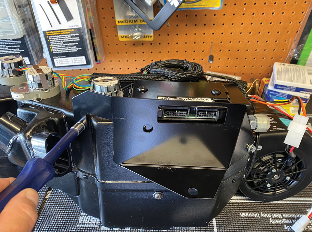
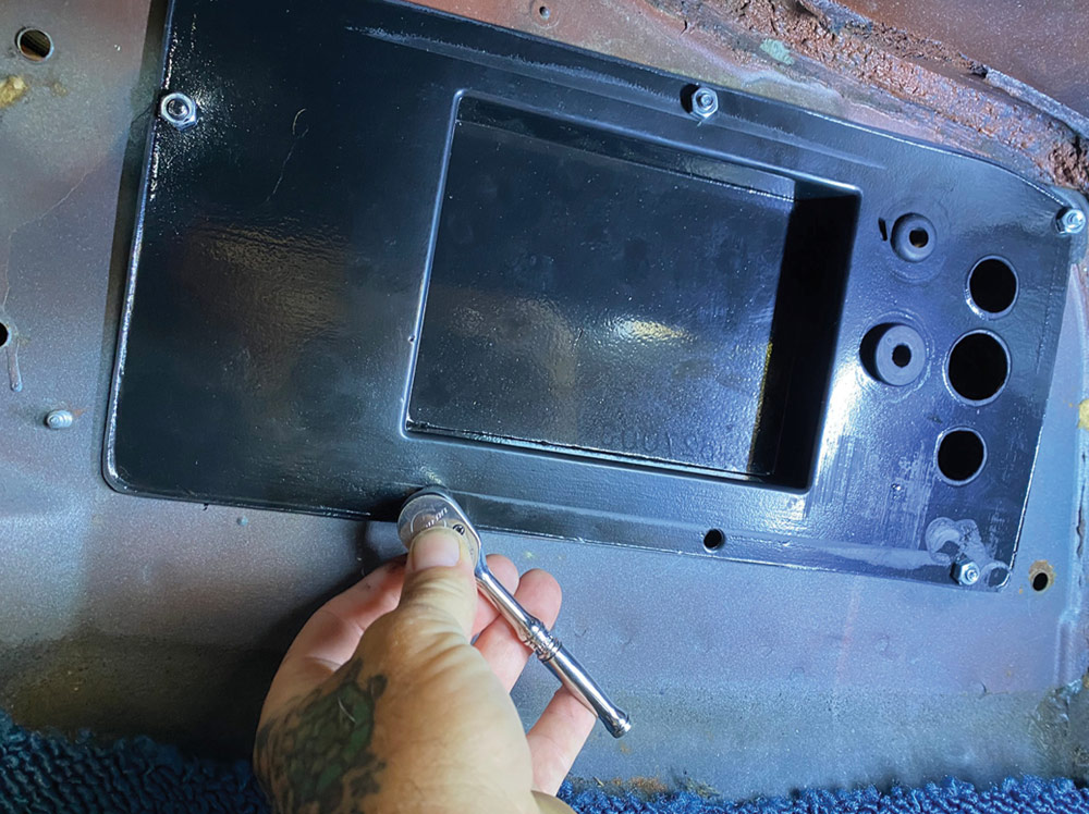
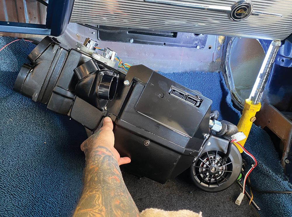
As far back as 1976, Vintage Air has been supplying universal aftermarket A/C systems to make it easy for enthusiasts to keep their early cars and trucks cool. Since then, Vintage Air has continued to incorporate the latest technology in their product line. As an example, at one time OEM and aftermarket climate-control systems used cables or vacuum motors to control the doors that directed airflow in the evaporator case—both systems had limitations due to the limited movement of those doors. Vintage Air’s Gen II and IV systems use fully electronic microprocessor-controlled servo motors to control the operation of those doors, which allows them to travel further. The results are dramatic gains in airflow, superior defrost performance, and true bi-level operation in both heat and A/C modes. Today that technology has been combined with Vintage Air’s SureFit vehicle specific kits that are complete, bolt-in climate-control systems that require no significant modifications to the car (some holes may have to be drilled).

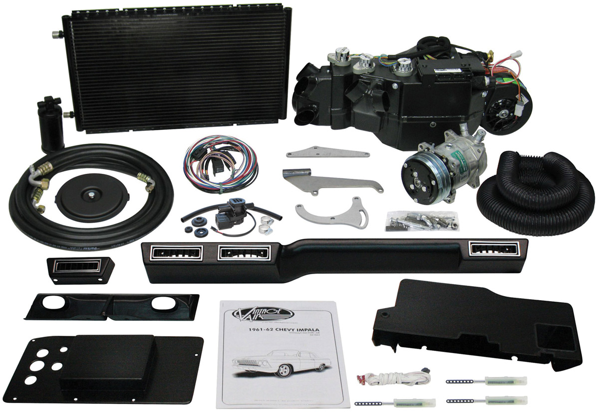
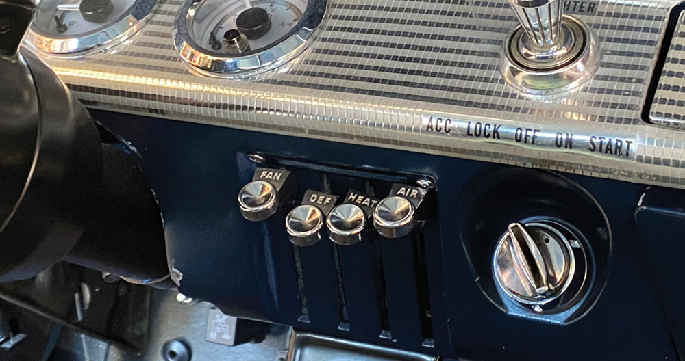
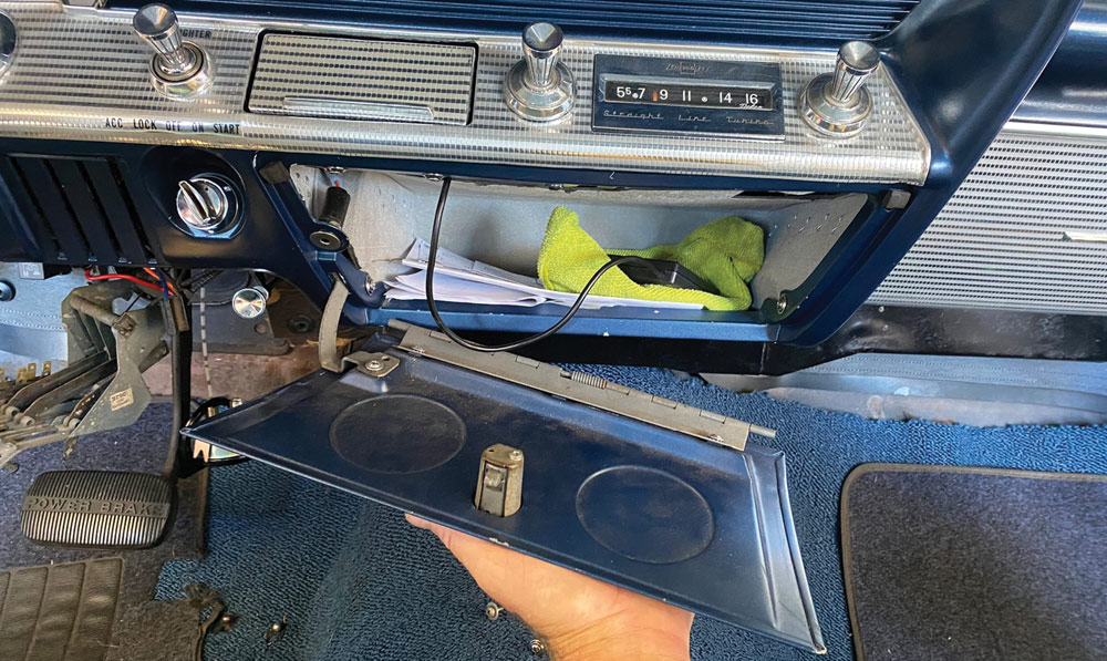
Available for a wide variety of cars and trucks, the SureFit system shown here is for ’61-62 Chevrolet Impalas without factory air (PN 561062). For cars with factory air, Vintage Air offers systems (PN 964062) that use the factory A/C outlets. As with all SureFit systems full OEM-style operations include infinite air temperature blending, infinite blower fan speed adjustment, and high-volume dehumidified defrost mode.

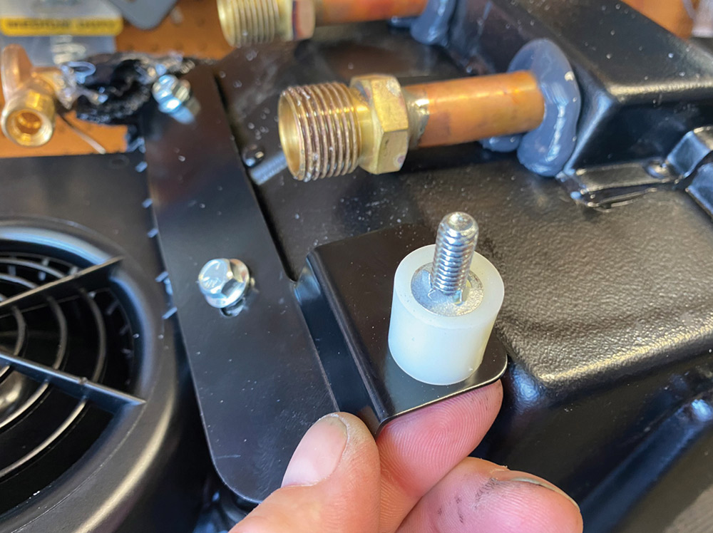
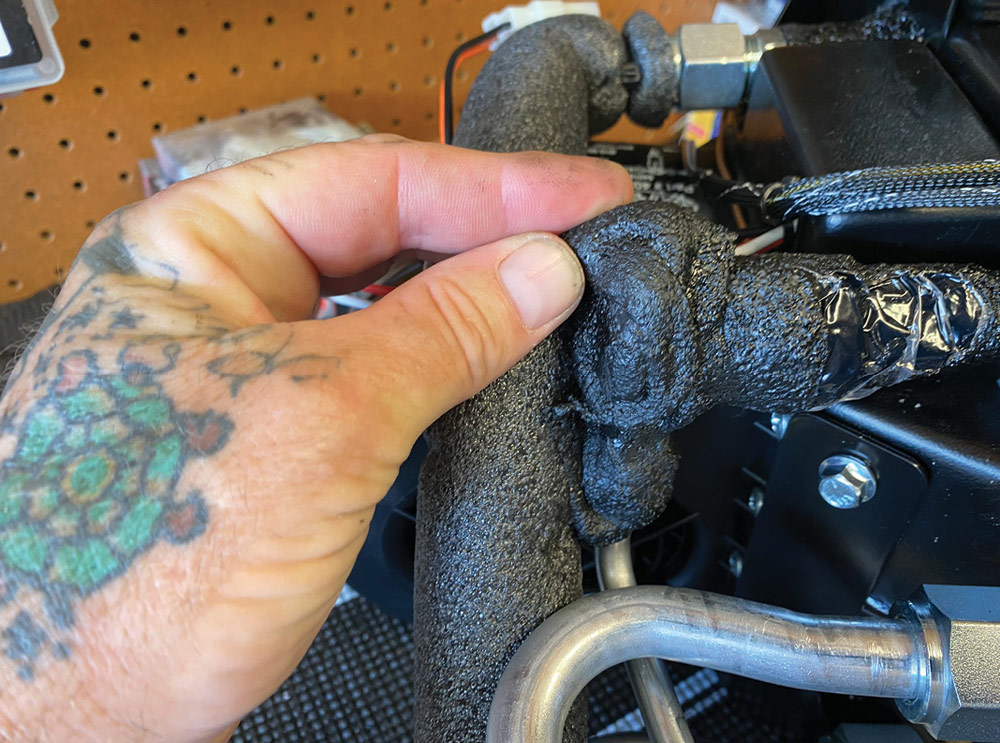
While Vintage Air has made installing a contemporary climate-control system as simple as possible, there are a few additional considerations that will ensure it operates at peak efficiency:

Insulation/Weatherstripping
In operation, an A/C system takes in air from a confined area, pushes it across a coil in the underdash evaporator where the heat is absorbed and the humidity converted to water droplets that drain to the outside. Cooled air is then pushed out through the vents onto the occupants while the heat is carried to the condenser in front of the radiator. It stands to reason that minimizing any additional heat source will make the A/C system more effective so it’s important to insulate the firewall, floor, doors, roof, and make sure all the weatherstrips are in good condition; tinted windows will also help.
Electrical System Requirements
Our Vintage Air SureFit system requires a constant 12V source and a dash light feed. While that is simple to install, the sophisticated electronics require a stable power source and good grounds to eliminate the possibility of any electrical feedback that may cause erratic operation. An alternator is also a necessity as the original generator will not provide enough amperage to support the system.
Receiver/Drier Installation
The Receiver/Drier filters the refrigerant, separates vapor from liquid refrigerant, and removes moisture. It has an arrow indicating the direction of refrigerant flow and must be oriented within 30 degrees of vertical and mounted where it will be exposed to cool air, if possible.
Heater Control Valve Orientation
Installing the heater control valve incorrectly allows hot water to circulate through the heater core warming the air that the A/C is trying to cool. Most water pump heater hose outlets are on the low-pressure (suction) side of the pump. The intake manifold outlet is the high-pressure side of the system. As water pressure in the hose helps the valve seal, if they are installed backward, or in the wrong hose, they will not shut off completely and some hot water will continue to flow.
Always Install a Compressor Safety Switch
There are two types of safety switches: Binary switches protect the system from excessively high (406 psi) or low (30 psi) pressure; trinary switches provide the same high and low protection, plus an electric fan engagement signal at 254 psi (on high pressure side).
Proper Evacuating and Charging
Leaving air and water in the system will reduce the efficiency of an A/C system dramatically. Evacuating the system with a vacuum pump for 45 to 60 minutes removes air from the system while the vacuum lowers the boiling point of water, so any moisture in the system boils away. To accurately determine if an A/C system is charged properly, dedicated gauges that show low and high side pressures are required. A general rule of thumb is high side pressure is two times ambient temperature plus 15 to 20 percent. An overcharged system (too much refrigerant or oil) results in higher system operating pressures and poor performance. An undercharged system will show lower operating pressures and poor performance as well.
Adding Oil to the Compressor
New Sanden Compressors from Vintage Air come with the proper amount of oil, so an additional amount isn’t necessary. Adding more oil can result in excessive system pressure, which results in poor system performance. If you are using an OEM compressor in your system, follow the manufacturer’s recommendations on oil capacity.
Follow the Instructions
We’ve all heard this one: Before you begin installation, read all the instructions, warnings, labels, and any other printed material included. Then, familiarize yourself with all the components before you start. If you still have questions, get them answered before proceeding. The Vintage Air tech guys would rather prevent a problem than cure one.

Installing a Vintage Air SureFit system is a great way to get all the benefits of a contemporary climate-control system in your classic Chevy without making major modifications to the car. Think of it as a personal environmental impact statement.

Vintage Air’s complete SureFit kit components
2. Vintage Air’s complete SureFit kits for ’61-62 Chevrolet Impalas use Gen IV technology with fly-by-wire electronic servo motors to operate the doors that direct airflow. The system is controlled by a sophisticated ECM mounted to the housing.
Electronic cable converters and switches
3. Vintage Air’s patented electronic cable converters included in the kit change mechanical movement of the original controls into an electronic signal.
New AC switches installed
4. After modification, the control panel retains the look of the original while operating all the features of the new Vintage Air system.
Removing stock glovebox door
5. To begin the evaporator installation the stock glovebox was removed. It will be replaced by a new, smaller version that comes in the kit.
Removing stock heater plenum
6. This is the stock heater plenum; it is removed along with the original defroster duct—they will be replaced with new components. The radio and speaker are also removed but will be replaced.
Removing stock blower motor assembly from engine bay
7. From the engine side of the firewall the original blower motor assembly is removed.
New evaporator case bracket
8. The new evaporator case has a pair of brackets that attach to the firewall.
Underside of new evaporator
9. This large bracket attaches to the evaporator to the lower edge of the dashboard. The rectangular hole (arrow) provides access to the unit’s electrical connections.
Installing firewall cover plugs
10. The supplied firewall cover plugs the hole for the original heater and provides mounting points for the evaporator case and holes for wiring, A/C, and heater hoses.
Spacer bolt on rear evaporator bracket
11. For proper placement, a spacer is used on the rear evaporator bracket. It may be necessary to remove the factory insulation retainers if they interfere with the Vintage Air mounting brackets.
Insulation on suction lines
12. The included press tape is used to insulate the #10 suction line to prevent condensation. The expansion valve is insulated protecting it from ambient temperature as it senses the temperature of the refrigerant in the return line and regulates flow.
Evaporator case ready to be installed
13. When installing the evaporator case, it should be level and square to the dashboard so any moisture accumulating in the case will drain properly.
Drain hose running through new firewall hole
14. A hole is drilled in the base of the firewall for the drain hose that comes from the bottom of the evaporator case.
Installing a duct hose
15. When installing duct hose, stretch it tight to make it as smooth as possible, then measure, mark, and cut it to the appropriate lengths. Keep in mind bends and kinks are obstructions to airflow; when bends are necessary, make them as smooth and gentle as possible and support the hoses, if necessary, to prevent “drooping.”
New louvered outlets being installed
16. Our ’61-62 Impala non-original A/C kit included driver side and center/passenger side louvered outlets. Kits for factory A/C cars use the original outlets.
Engine compartment line connections
17. The engine compartment connections are: ⅝ intake heater line, #10 A/C suction hose, #6 evaporator high-pressure liquid line, and ⅝ heater return line.
New parallel-flow condenser
18. Vintage Air’s parallel-flow condenser should be mounted with the tanks vertical and the tubes horizontal. The larger #8 discharge fitting from the compressor should be on top and the smaller #6 liquid line fitting will be on the bottom (this one is viewed from the engine side).
Installing refrigerant canister and hardlines onto condenser
19. Included in the SureFit kit are pre-bent drier and condenser hardlines and the required hose for the specified 134a refrigerant.
Tightening A/C fittings
20. When installing A/C fittings the O-rings must be lubricated with compressor oil and overtightening the fittings must be avoided. Be sure to always use a backup wrench on the mating fitting.
Heater control valve
21. The Vintage Air heater control valve is directional and must be correctly oriented in the high-pressure heater hose.
Installing heater control valve into hose
22. The heater control valve is installed with the servo motor facing down. It is controlled by the ECM on the evaporator case.
Trinary pressure safety switch
23. Vintage Air systems come with a binary pressure safety switch. A trinary switch with an electric fan operation signal is available as an option.
Installing fan onto condenser
24. If your car has overheating problems, it won’t get better with A/C. To ensure proper airflow through the condenser, install the most effective fan possible (mechanical or electric) with a shroud and position the condenser ½ to ¾ inch in front of the radiator.
SOURCE
Vintage Air
(800) 862-6658
vintageair.com