ACP department heading TECH
InTheGarageMedia.com
Vintage Air AC unit ready for installation with instructions
Hunting Down Creature Comforts in a Handyman Wagon typography
Part 2: Wrapping Up the Installation of Vintage Air’s Gen 5 SureFit Kit in a 1957 Chevy
BY Ryan MansonImages BY THE AUTHOR
L

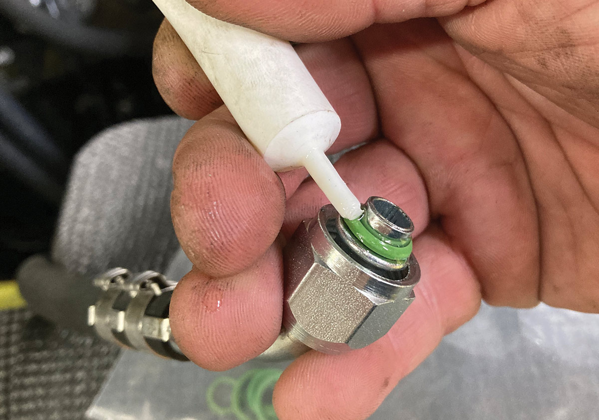
ast month, we concluded the installation of a Gen 5 Vintage Air SureFit kit in our 1957 Chevy Handyman Wagon by installing the evaporator unit. The defroster vents were installed and hoses attached, as was the center vent, and hoses were routed in preparation for the side vents. The drain was in place to route any condensation outside the vehicle and the four hard lines were installed and routed through the firewall. It would seem that we were on the downhill slope, and for all intents and purposes, we were, but there’s still a lot of work to be done.

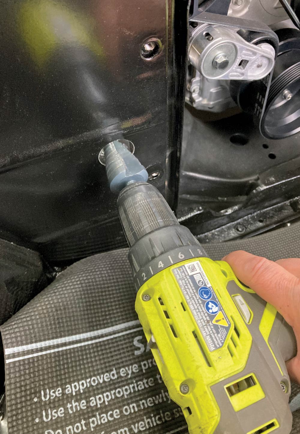
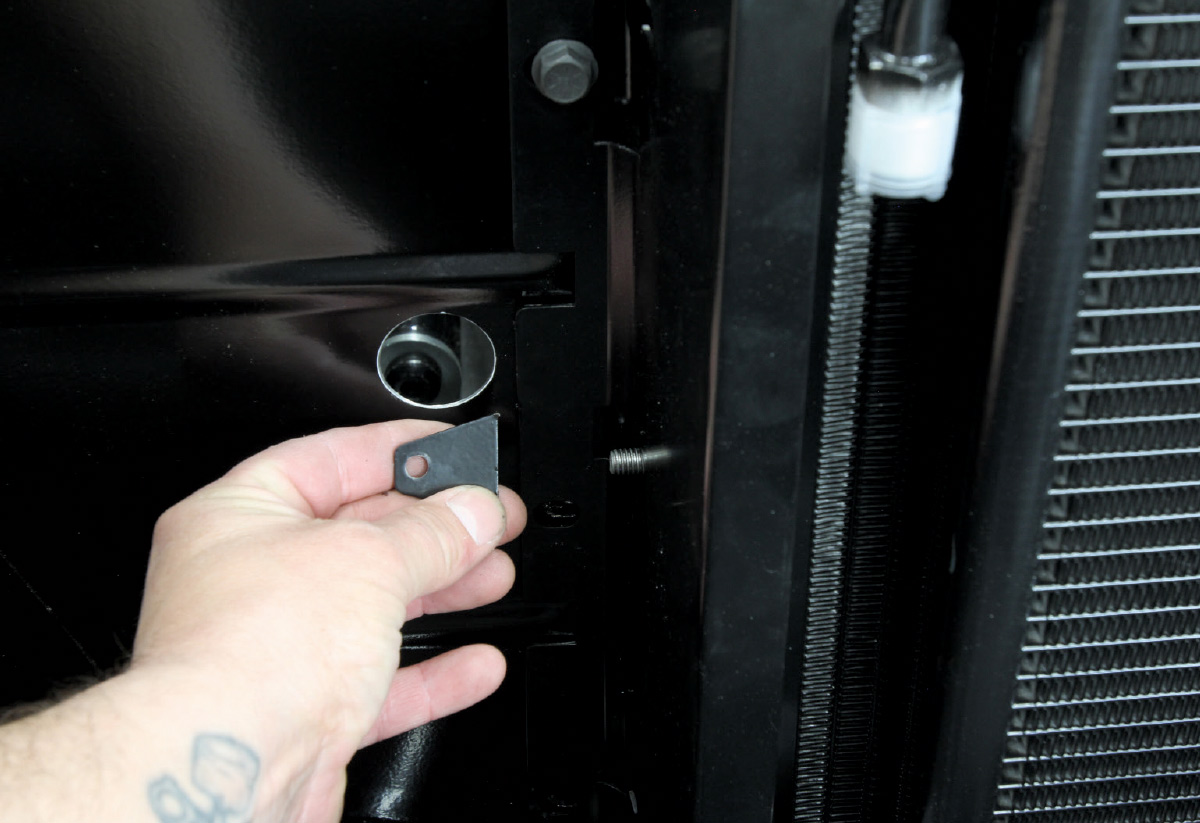
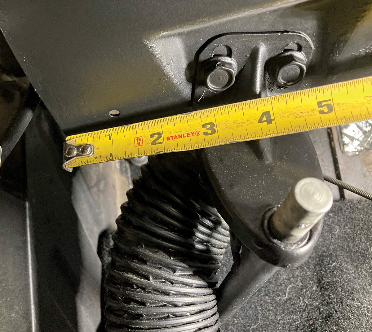
For starters, we still need to install the radiator and condenser unit. The previous small-block that was in our 1957 had a meager mechanical fan that pulled just enough air to keep the mild motor happy. With the installation of a hot-rodded LS3, this obviously wasn’t going to do, so we turned to DeWitts to help us sort out our cooling requirements. Since the addition of the A/C and its requisite condenser will add some additional heat load to the overall system, it’s paramount that the cooling system be at peak performance to ensure the A/C system blows air as cool as the Arctic snow. DeWitts’ recommendation of their LS Swap Aluminum Radiator with included electric fan filled the required void with room to spare

With that tackled, it’s time to turn our attention to the various hoses required in the system. While the heater hoses are pretty standard fair, the A/C system’s hoses are not. There are two types of hoses generally found in automotive A/C systems: Beadlock and E-Z Clip. Beadlock has been the industry standard for years but requires expensive tooling to provide the required crimp. E-Z Clip on the other hand can be assembled using a handheld, affordable crimper and a handful of components. The E-Z Clip hose is also slightly smaller in diameter and more flexible, making it easier to route through tight spaces.

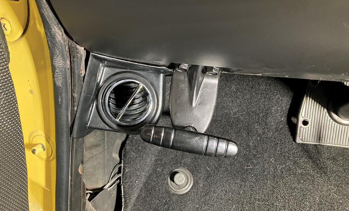
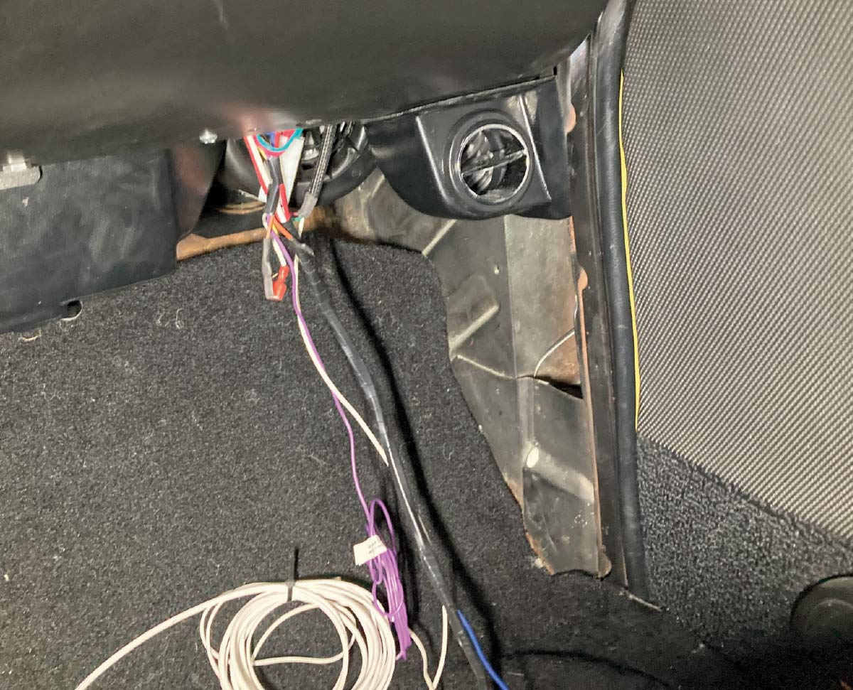
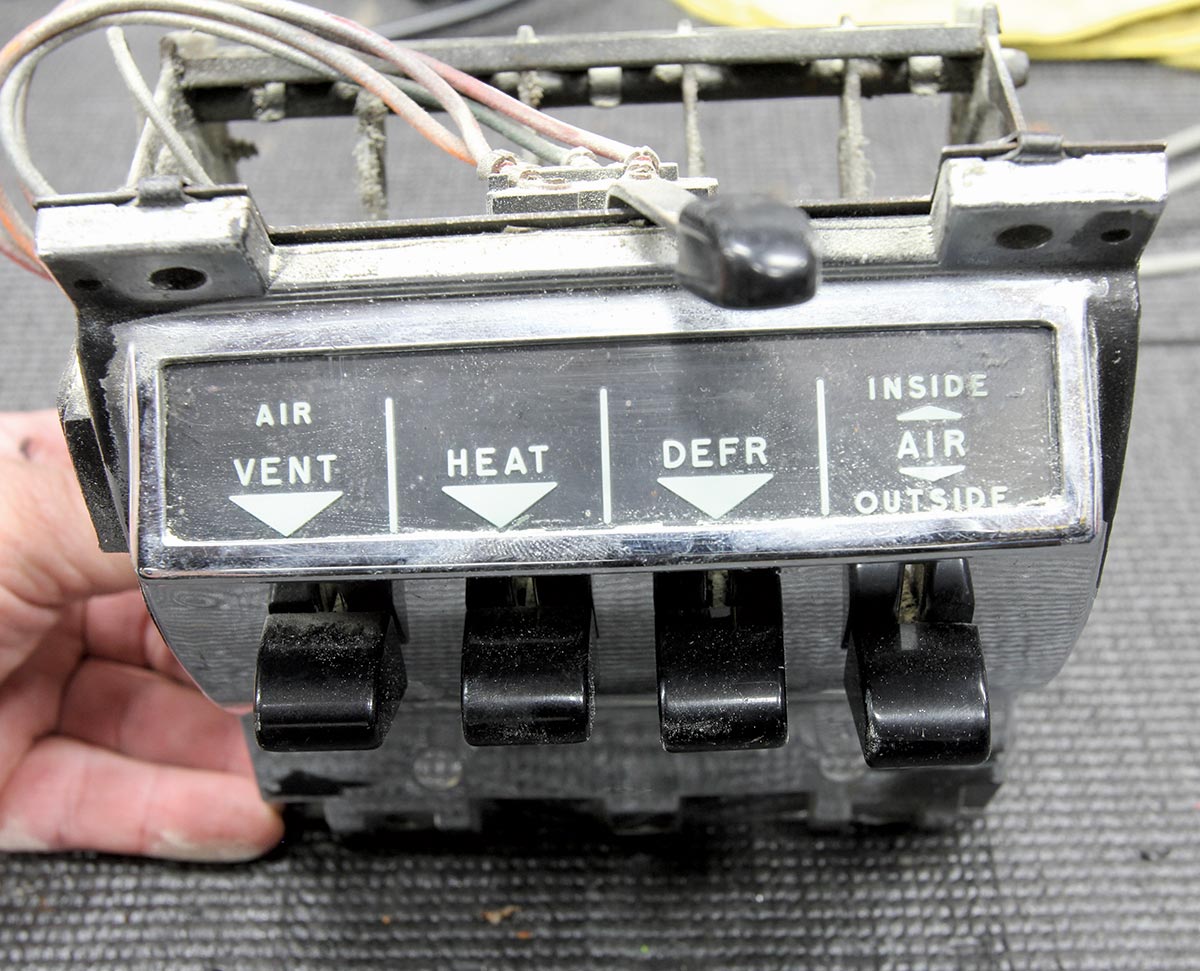
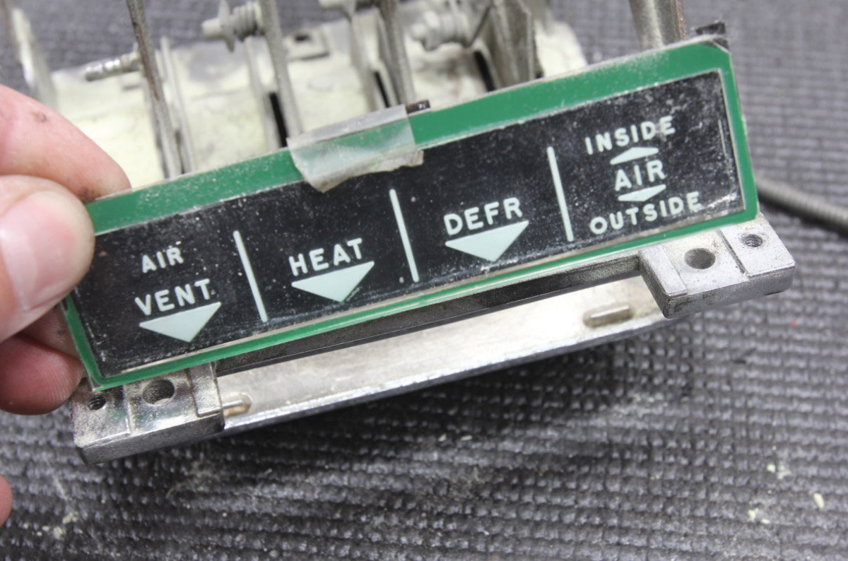
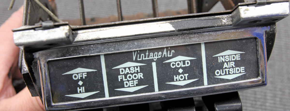
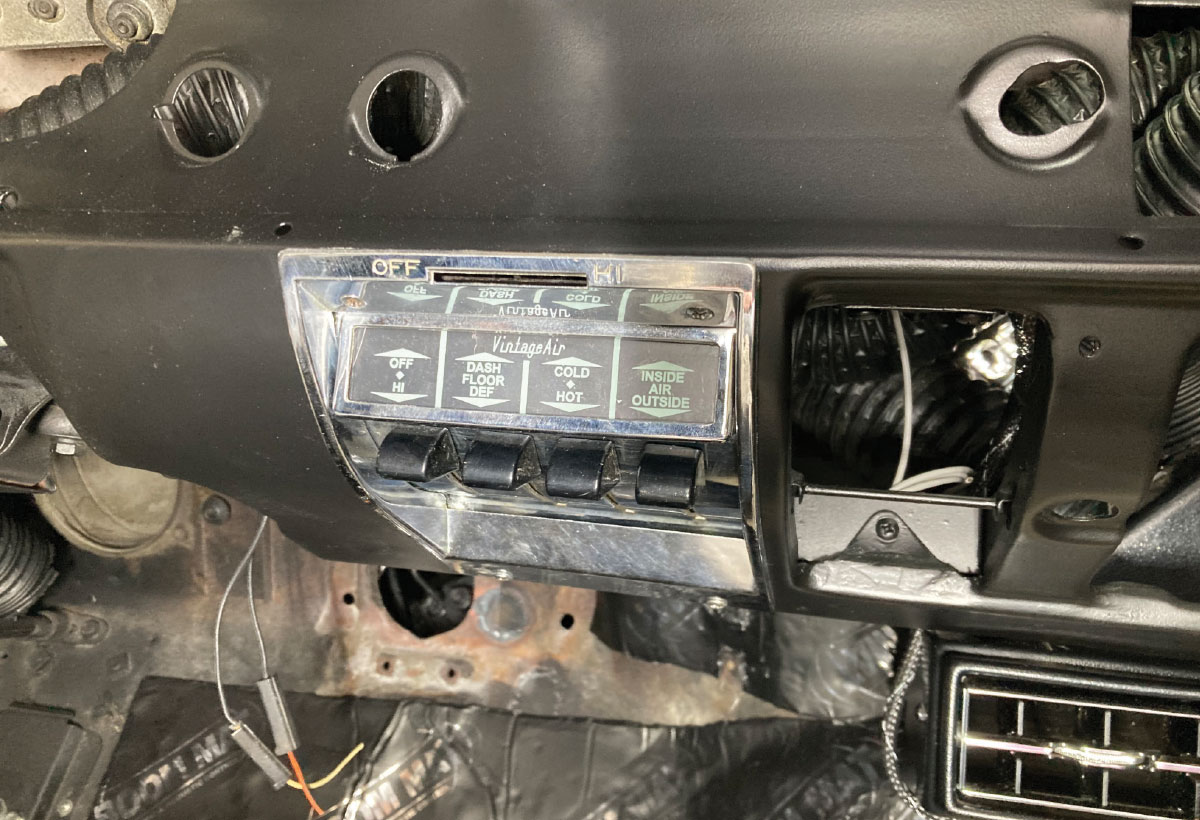
Once the system was plumbed, our attention turned to the inside of the car where the wiring was buttoned up and the control panel modified to accept the electronic cable converter assemblies that will translate the position of each lever to the evap unit’s ECU communicating the changes desired electronically, whether they be in the mode, temp, or blower speed realm. At this point, the two side louvers are installed using Vintage Air’s provided brackets and components and the remaining ducting ran to each.

Satisfied with our install, we made the short trek to our local automotive A/C shop where they charged the system with 1.8 pounds of R134a, no more, no less. After a run-through of the calibration sequence to ensure the ECU is receiving the proper signal from the control panel, we were happy campers, cruising cool with our newly climatized Chevy.

Restored radiator with an electric cooling fan mounted
1. A/C condensers can generate a fair amount of heat, and that only adds to the heat generated by the engine. Thus, it’s important to have a cooling system that operates as efficiently as possible. For that end, we turned to DeWitts and ordered one of their LS Swap Aluminum Radiators finished in black (PN 32-6239013M). The serpentine fins and brazed construction, with factory-type press-formed upper and lower tanks, provide not only a factory look but an increase in cooling performance. When ordered in conjunction with their electric fan kit, the DeWitts radiator setup ensures that not only will the temps of our LS3 engine be sufficiently controlled, but our A/C system will be operating at peak efficiency.
Close-up of radiator fittings and overflow tube
2. One of the features of the Dewitts LS Swap Aluminum Radiator is the inclusion of a steam line vent tube and coolant temp sensor bung in the top tank.
AC condenser mounted on a workbench before installation
3. Here’s the assembled Vintage Air A/C condenser and bracket assembly ready to install. Note the larger #8 line is at the top of the passenger side.
Drilling mounting holes for the AC condenser brackets
4. The triangular break-off tab on the passenger side of the condenser assembly serves as a locator for the hole that will be used as a pass-through for the A/C hard lines. With the condenser assembly temporarily installed, using the tab as a guide, a 1/4-inch pilot hole is drilled.
Step drill bit used to enlarge firewall hole for AC lines
5. The condenser assembly is then removed so that the hole can be enlarged to 1 1/4 inch.
Installing a mounting bracket near the radiator
6. The break-off tab is then removed and the condenser assembly reinstalled.
AC condenser and radiator installed in the engine bay
7. On the opposite side of the core support, the drier assembly has been installed using the bracket provided by Vintage Air.
Vintage Air dryer mounted in the engine compartment
8. Here’s the radiator and condenser assembly installed and ready to be plumbed. Note we installed the radiator in front of the core support, a necessity due to the front pulley system and electric fan arrangement.
Pressure switch and fitting for the AC system before installation
9. Since we want the electric fan to be triggered by A/C pressure as well as engine temperature, we will be using a trinary safety switch. These can be installed directly into the side port on the drier or inline using the parts pictured.
Pre-bent aluminum AC hard lines with protective caps
10. Accurately bending hard lines can be challenging for even the most advanced builders. Thankfully, Vintage Air provides pre-bent hard lines where required; two at the evaporator (previously installed) and two at the condenser.
AC condenser installed with new hard lines connected
11. In this case, the #8 condenser/compressor hard line and the #6 condenser/drier hard lines have been installed and pass through the core support. The condenser/drier hard line will connect directly to the drier, while the condenser/compressor hard line will connect to a hose that will route to the #8 connection on the compressor.
AC bulkhead fittings routed through the firewall
12. The other side of the drier will connect to a hose that will terminate at the #6 hard line poking through the firewall from the evaporator. This is referred to as the high side of the system. The other side of the compressor will also terminate at the evap unit (top fitting). This is the largest of the three hoses (#10) and often referred to as the low side.
Rubber AC hoses ready for installation
13. Generally speaking, there are two common hose types that are used in automotive A/C systems: crimp-type Beadlock and E-Z Clip. We prefer the E-Z Clip style due to the smaller hose diameter, increased flexibility, and simplicity of installation. Pictured here are the #6, #8, and #10 hoses that we’ll be using. Note that the hoses between the two styles are not interchangeable and require their own respective fittings be used.
Various AC hose fittings and adapters laid out
14. E-Z Clip fittings are available in a variety of radius bends with and without charge ports.
AC fitting with clamps and retaining clip
15. The business end of an E-Z Clip hose consists of the hose fitting, cage, and two clips.
Crimping tool securing an AC hose fitting
16. After the length of the hose is determined, a nice, square cut is made …
Hand-fitting a hose onto an AC fitting
17. … before the hose is slid onto the fitting. I like to apply a touch of O-ring oil on the fitting to ensure the hose goes on easily and doesn’t damage the O-rings on the fitting.
Crimping clamps secured around the AC hose fitting
18. Next, a cage and two clips are installed and crimped in place using a specialized E-Z Clip tool.
Completed AC hose assembly with crimped clamps
19. With that, we have a finished hose end without the expense of specialized crimp tooling.
Applying lubricant to an AC fitting O-ring for proper sealing
20. That same O-ring oil is always used on every O-ring fitting in the system to prevent damage due to dry O-ring installation.
Installing an electric water valve with hose clamps and wiring
21. Heater hose installation is standard procedure, with the addition of a heater control valve that must be installed in the high-pressure (usually an intake manifold port) side of the system with the molded coolant flow arrow pointed to the heater coil. Note the orientation of the heater valve, with the electronic portion of the valve above the water line. This is to prevent failure of the electronics if a leak is developed.
Measuring firewall clearance for AC component installation
22. Turning our attention inside the wagon, it’s time to mount our side louvers. A 7/32-inch hole is drilled in the bottom of the dash rail, ³/8-inch outside of the existing OE hole.
New under-dash AC vent installed near the driver’s side
23. The louver assembly is then combined with the provided aluminum bracket and installed.
Centered AC vent installed under the dash for airflow distribution
24. We installed the center louver assembly last time, but here it is again for reference.
Passenger-side AC vent installed with wiring routed
25. The passenger side louver is installed in the same manner and thus completes our installation. But, while we’re at it, we should cover the wiring side of the installation. A violet wire provides 12 V switched to power on the unit and should be connected as such. A small tan wire will be connected when a Vintage Air control panel is used to provide dash backlight power. A separate group of violet/yellow/white wires will pass through the firewall and connect to the heater control valve. Connecting to the trinary switch is a blue wire, the opposite side of which will be run to the compressor. Two white wires need to be attached directly to Batt-, while the orange and red wires will be connected directly to Batt+, with the corresponding fuses in line for protection.
Old factory AC control panel removed for modification
26. A/C in the 1950s meant the coolest things we’re going to get was the temperature of the ambient air outside the vehicle. At peak season in Phoenix, this isn’t too comfortable of a situation. The stock heater control panel used cables to control the various functions. Using Vintage Air’s Control Panel Conversion Kit (PN 472058), we’ll be converting those mechanical functions with electronic ones. If you are looking for a more modern look on the dash, Vintage Air now offers a complete chrome-plated bolt-in replacement control panel.
Backside of the AC control panel being wired for Vintage Air conversion
27. Three cable converter assemblies have been installed per Vintage Air’s instructions. These will control the fan blower speed, mode, and temperature via the evap unit’s ECU.
Removing the original control panel label for a new overlay
Vintage Air control panel installed with updated functionality
28-29. Since the controls have changed regarding which knob controls which function, Vintage Air provides an updated placard that is swapped out for the original.
Vintage Air control panel installed in the dashboard, with additional vent and wiring modifications in progress
30. With our A/C plumbed and wired, the last piece of the puzzle is to finish assembling the dash. Note the inconspicuous nature of the retrofitted control panel, clearly marked for function without damaging the original aesthetic of the Tri-Five’s dash.
SOURCES