 TECH
TECH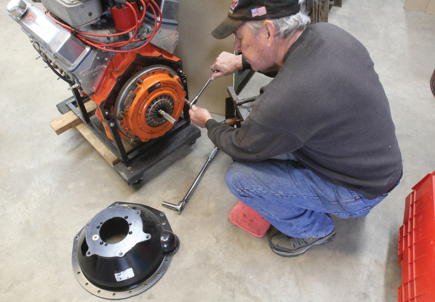
 By JEFF SMITH
et the new century prognosticators spew all they want about the demise of the traditional manual transmission. For those not quite ready for dual-clutch transmissions or care even less about 10-speed automatics, there is still much to celebrate for left pedal fans when it comes to the current crop of manual transmissions for hot street cars. What we will cover here is the friction connection between the engine and the input shaft of that manual transmission.
While dual-disc clutches might be cool and charismatic, it’s the basics about how clutches work that should be first on your list of crucial information. It’s important to understand the fundamentals of how clutches operate, and the variables involved with all the fundamental factors. Items like pressure plate design, clutch diameter, clamp load, friction material, operating temperature, and a host of other variables. Once you’ve cornered this area of expertise you will have a much better idea of which clutch will be the best one for your next project. All this makes a big difference when it comes to how you intend to use this clutch. We’ll look closer into these ideas and tie them all together to help weed out the unnecessary hype so you can choose the clutch that will best get the job done.
The amount of pressure plate force applied to the clutch is called the clamp load and is determined by the spring pressure applied by the pressure plate. The most popular basic pressure plate designs include the Borg & Beck, diaphragm, and Long style (also called a Ford lever). The Borg & Beck (sometimes called a Chrysler style) has fallen out of favor with most clutch builders, leaving the Long style as the popular racing pressure plate with the diaphragm as the most popular for the street.
The Long style uses three sets of coil springs that are controlled by a thin release arm tied to each of three sets of springs. This arm can be modified with additional weight to add rpm-based centrifugal force to the base clamp load for high-horsepower engines used in competition. The Long style is not a good choice for street operation, although it can be used. Mainly it often requires a fairly high pedal effort. As a final note, Long-style pressure plates employ a different attachment pattern than the Borg & Beck and diaphragm so these pressure plates are not interchangeable.
The diaphragm, also known as a Bellville spring, offers a significant advantage over the more traditional coil spring pressure plates. As a coil spring is compressed, load increases. However, with a diaphragm, once it reaches its center pivot point when the clutch is fully released, the load is drastically reduced. This allows the user to keep the clutch pedal in during street operation at a stoplight for example, without taxing leg strength as would be the case with a Borg & Beck or Long-style pressure plate.
Another major variable is the diameter of the clutch assembly. For mild V-8 street operation, 10½-inch clutches will easily get the job done. Larger engines generating more torque and horsepower increase this to 11- and 12-inch units. A larger diameter merely increases the clutch surface area, which increases its clamp load and therefore torque capacity.
This is a good place to mention that while clutches are generally rated by horsepower, it is really the engine’s torque that is the major factor for choosing a clutch. The more torque, the higher the twisting motion created by the engine which demands a more-aggressive clutch holding capacity. Remember that horsepower is merely torque over time expressed as work. This is also why clutch companies will want to know items like vehicle weight, gear ratio, as well as engine size and whether there is a power adder.
Increasing clamp load with higher pressure plate spring force is a simple way to hold more torque but this also increases pedal effort. Another option for clutch builders is to improve capacity with an increase in diameter or with more aggressive materials using a higher coefficient of friction. For street clutches, the traditional organic material continues to constantly evolve and is an excellent choice for mild applications as this material offers the advantage of smooth clutch engagement.
Other compounds, such as ceramics, Kevlar, and sintered iron offer a much higher coefficient of friction, which increases holding capacity. But these materials can make clutch engagement more aggressive and more likely to produce clutch chatter. Lately, several companies, such as Centerforce, McLeod, Ram, Spec, and others, now combine these more forceful compounds on one side of the clutch disc with more forgiving organic compounds on the opposite side. This accomplishes the goal of increasing the holding power while ensuring easy engagement.
You may have noticed that these combination clutch discs use a smaller area of ceramic or sintered iron face material. This is intentional since this concentrates a higher load (in terms of pounds per square inch) on the material to increase its operating temperature to ensure optimal performance. When combined with an organic clutch facing on the opposite side of the disc, the clutch can supply greater holding capacity without negatively affecting engagement or creating undue wear.
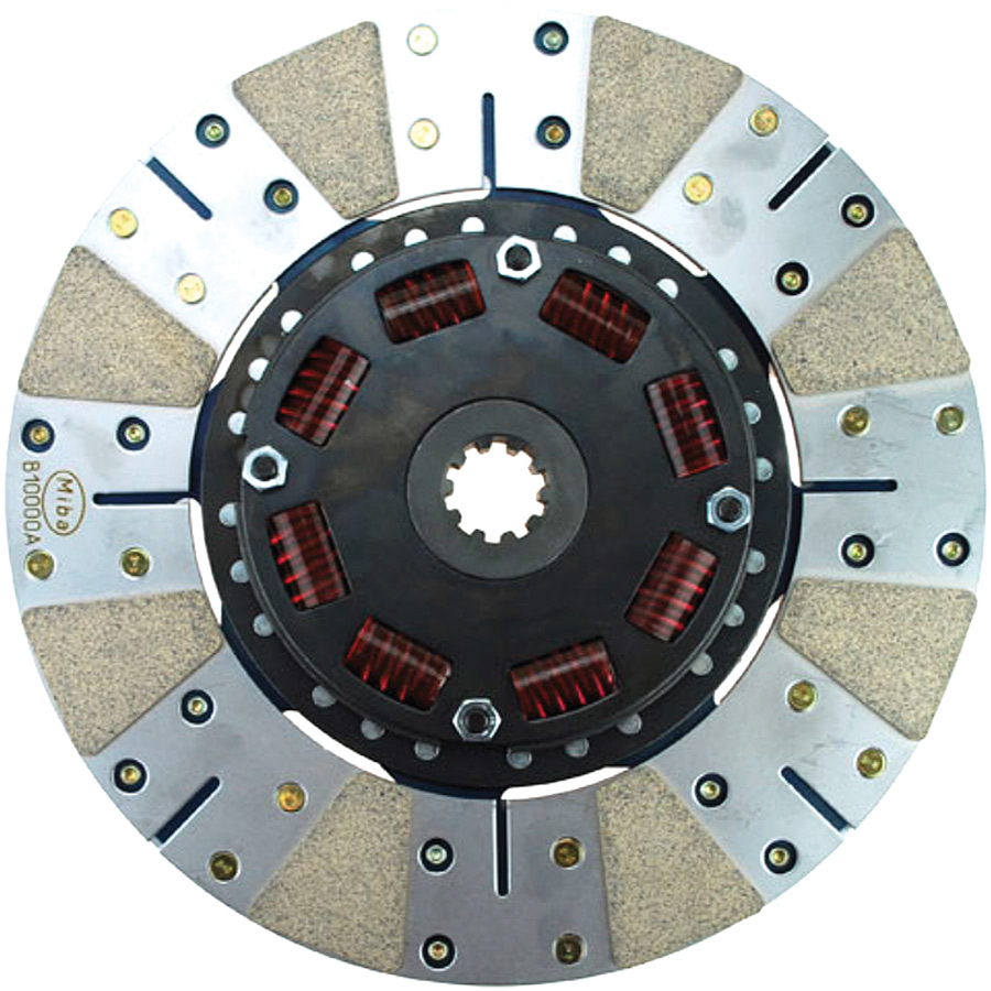
Within the clutch disc itself, there are multiple design functions at work. Nearly all street clutches employ what is called a sprung hub. The typical approach is six (and sometimes eight) coil springs placed between the input shaft of the clutch disc and the clutch facing. When the disc is loaded during engagement, these springs compress slightly and reduce or eliminate clutch chatter or shudder. An additional technique employs what is called a Marcel spring. This is a thin, wavy spring placed between the clutch face material and the clutch disc itself. This spring also improves engagement performance, making this process smoother and less intrusive.
One aspect that most generic clutch stories fail to address is how heat generated by the clutch affects holding power. Heat is a significant factor that directly affects overall clutch performance. Organic materials are used to enhance low temperature clutch engagement but are limited by a somewhat conservative temperature limit. This is why dual-friction–style clutches with an organic facing on one side and a ceramic material on the other have become so popular. Under high load, the clutch temperature increases, which bumps up the ceramic or sintered iron coefficient of friction, which improves the clutch assembly’s overall torque capacity. That’s why you will see the higher rated clutch assemblies using these more aggressive materials.
The trick is to choose the correct clutch assembly for your particular application without going overboard by “over clutching” the application. This is where a heavier duty clutch is misapplied when it’s not necessary. This can lead to engagement problems, clutch chatter, and a less-than-positive experience compounded by spending more money on a component that was misapplied, like trying to use a race clutch on the street.
Of course, choosing a clutch with less torque capacity than required can be equally as frustrating, often leading to slippage and clutch failure. This is why it’s important to discuss the application with your clutch company and to be completely honest with the vehicle specs and how it will be used. A clutch intended mainly for road course use with only occasional street time is a very different application from a clutch where it is mainly a boulevard cruiser with only occasional trips to the track.
Flywheel weight is another important consideration. Several poorly conceived media stories have appeared over the years touting the acceleration benefit of lightweight aluminum flywheels. What these stories rarely address is the loss of inertia momentum created by a lightweight flywheel. This is instantly recognized in normal driving when typical off-idle engine speed engagement results in an engine that easily stalls. With a lightweight flywheel, a much higher engine rpm is needed to build sufficient inertia to easily accelerate from a dead stop. This is why OE flywheels are usually heavier. This additional mass stores energy in the flywheel, allowing the engine to allow clutch engagement at just above idle speed.
As an example, a typical small-block Chevy 11-inch flywheel usually weighs 30 pounds with a complete clutch and pressure plate assembly scaling in roughly 45 to 50 pounds. By reducing the weight of the steel flywheel to 25 pounds, this can improve acceleration while still retaining sufficient mass to allow for normal street operation. Of course, this can also be achieved with a lighter pressure plate.

Companies like Centerforce, McLeod, Ram, Spec, and others offer several tiers of single-disc clutch assemblies that are aimed at a particular power level and vehicle application. For example, McLeod offers four levels of street single-disc clutches from Street Level to Extreme Street. Centerforce also offers similar packages with Centerforce I, II, and Dual Friction kits and Ram has three levels. Each is aimed at a particular performance level to help you match the right clutch for your situation. These kits are rated by horsepower but it’s still best to discuss your application with the clutch company for a specific recommendation.
This basics story has really just skimmed the surface of how the various details affect clutch performance, but this information should offer a solid foundation from which to begin the search for the right clutch. A basic understanding of how clutches operate makes the decision process much less confusing.
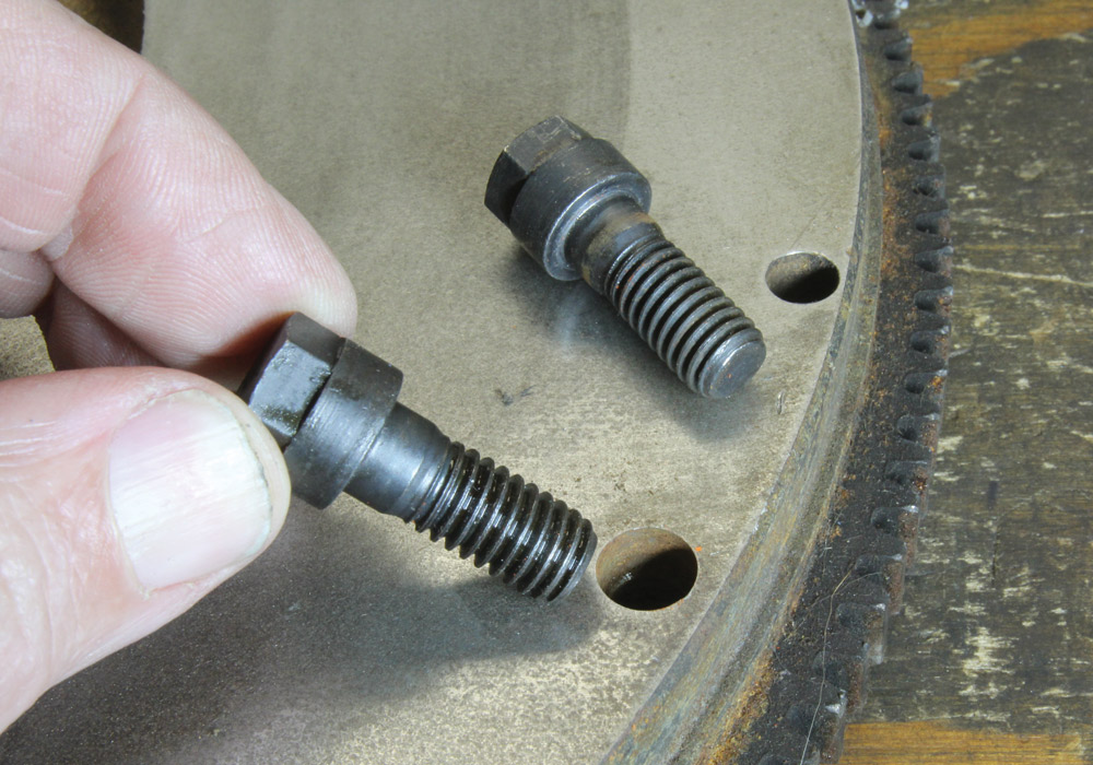
Most new clutch assemblies supply the proper pressure plate bolts. If you are mixing and matching parts, make sure to use the correct fasteners. Never use locking star washers under the flywheel attaching bolts. Always use a new release bearing with a new clutch. This is just cheap insurance. Many companies like Centerforce, McLeod, and others supply a new release bearing with the clutch along with a plastic dummy shaft to align the clutch pedal with the pilot bushing. Check with the clutch company because if the clutch does not come with one, you will certainly need one to complete the installation.
For older muscle cars using a release arm, carefully inspect the arm for wear marks or cracks around the pivot point and where the arm contacts the release bearing. It’s also a good idea to replace the ball stud that the release arm pivots on. This is a universally overlooked part that is often extremely worn. Replace both it and the release arm if there is any question. Your clutch will thank you for your attentiveness.

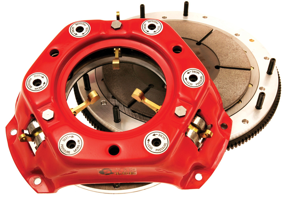
1. The basic clutch assembly consists of a flywheel, clutch disc, and a pressure plate. When the pressure plate is torqued to the flywheel with the clutch disc in between, the springs inside the pressure plate clamp the clutch disc to the flywheel, creating a clamp load that must withstand the forces of engine rpm, torque, and load of the vehicle.

2. This Summit Racing illustration shows a cross-section of a typical diaphragm clutch assembly with the clutch pedal pushed in. The release bearing has moved toward the left, which pushes the fingers of the pressure plate inward to release the clamp load on the clutch. If you look closely, you can see free space between the clutch disc and both the pressure plate and the flywheel.

3. This image shows a diaphragm-style pressure plate spring, which offers a major advantage of street operation.
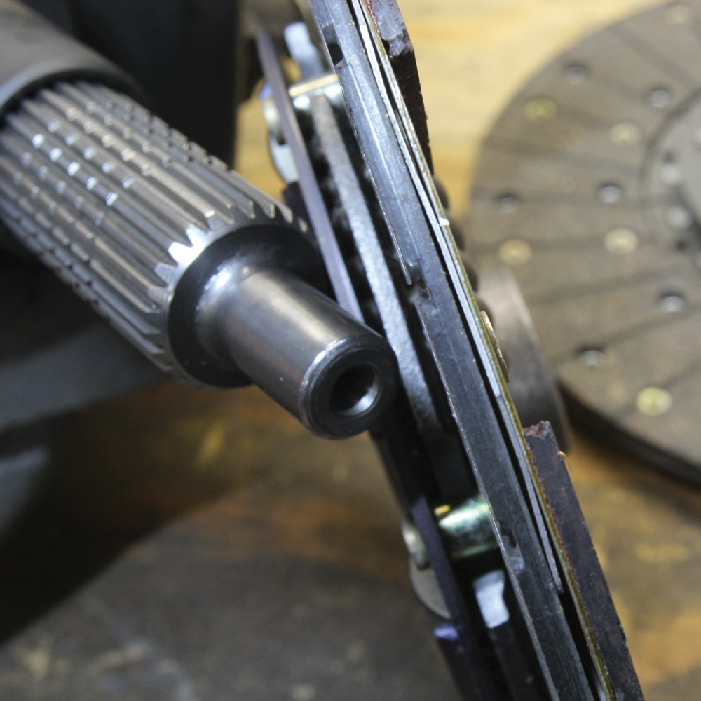
4. Here is a Long-style pressure plate with three fingers. The fingers control three sets of coil springs that produce the clamp load. The Long-style clutch is most often employed in drag racing applications because the load can be easily tuned for both static and high-rpm centrifugal load.


 SOURCES