
 Photography by The Author
t is the way of the world today. Technology improves the breed. Flat tappet cams had their day but if performance is your goal, one step that can really complement a good set of cylinder heads is the upgrade to a hydraulic roller cam. Yes, the cost to convert to a hydraulic roller is higher than just replacing a flat tappet cam. But there are multiple advantages to a hydraulic roller cam engine that we’ll go over before we show how easy it is to convert an ’86 and later model 350ci small-block Chevy over to a roller.
To update a pre-’86, two-piece rear main seal small-block Chevy to a roller, beyond just the cost of the cam and lifters, the conversion will also require a reinforced timing cover and a cam button to limit forward cam movement. This requires a button that presses against the inside of the timing cover to minimize forward cam travel.
The addition of a cam button is critical because flat tappet cam lobes are ground to offset the forward motion created by the distributor gear. But roller cam lobes cannot be ground with a taper so a button must be used to limit that forward motion. If the button is not used, the cam moves forward as rpm increases, which will radically retard the ignition timing. This can be as much as 20 degrees of retarded timing, which is why the effort to install a cam button is so important.
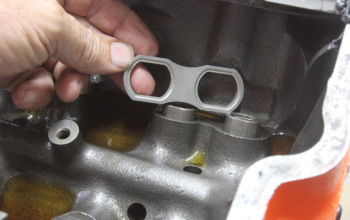
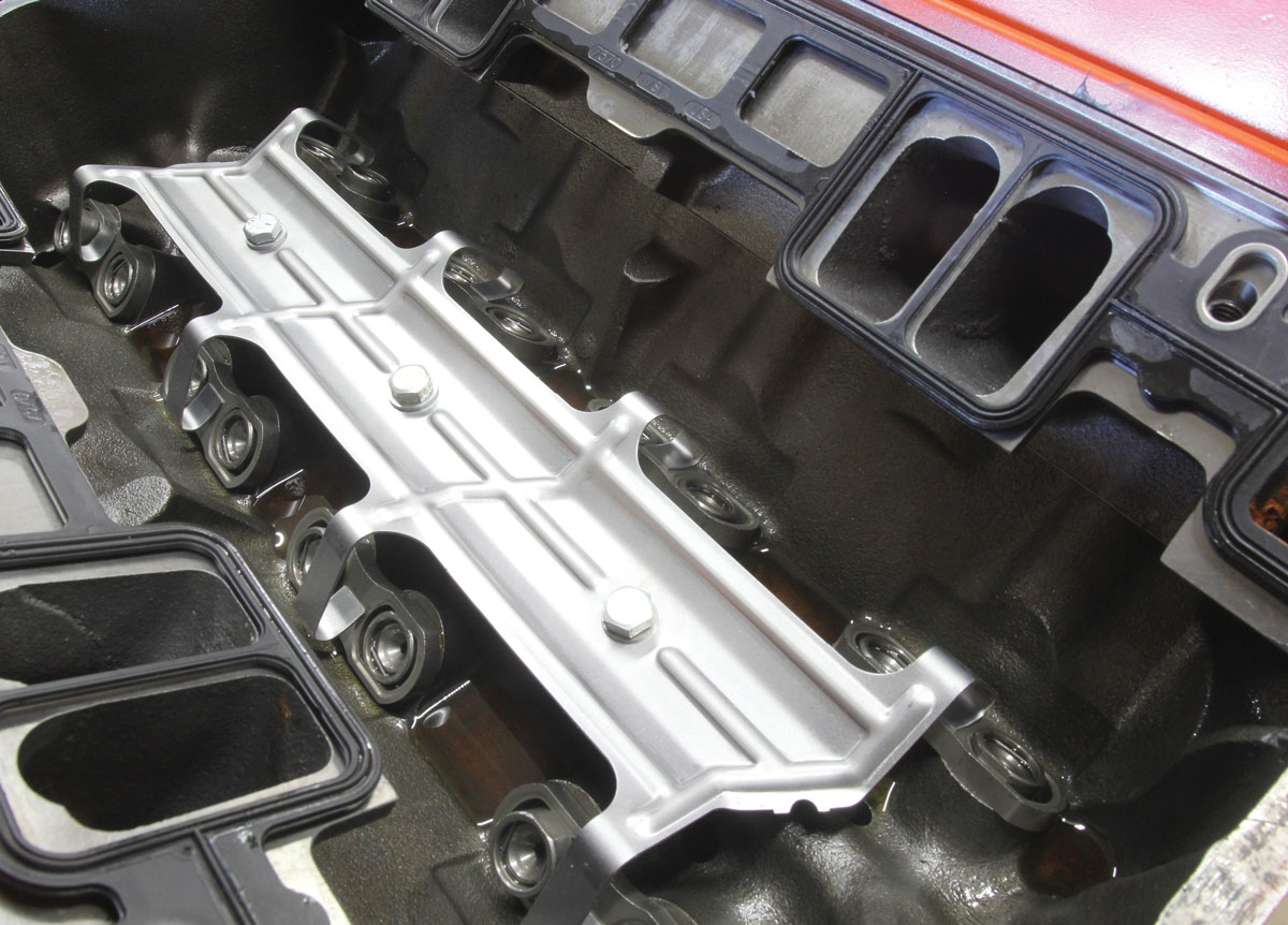
Beginning in 1986, Chevrolet upgraded the original small-block to a one-piece rear main seal and also modified the block to accept a hydraulic roller cam. Rather than using linked hydraulic roller lifters like the aftermarket, Chevrolet used pairs of what are called dog bones that slip over the squared upper lifter bodies to align the rollers to the cam lobe. Then a large spring called a spider with eight legs bolts over the dog bones to keep them in place.
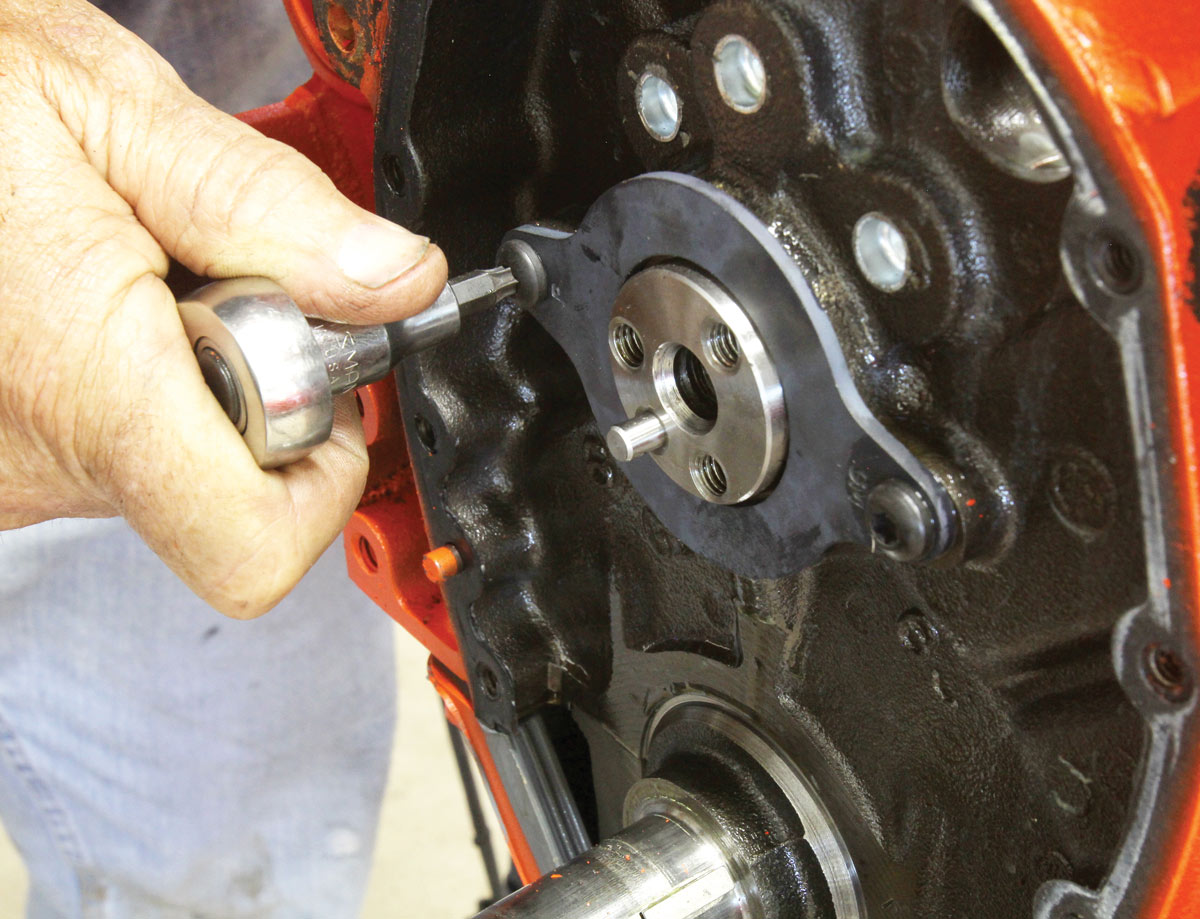
To limit cam movement, Chevy engineers used a simple steel plate that bolts to the front of the block to retain the camshaft in its preferred location. This demanded a stepped nose configuration on these newer engines, which requires a matching cam timing gear with a smaller bolt circle compared to the original small-block pattern.
Many of these one-piece rear main seal engines were used in trucks but were fitted with flat tappet cams. However, all the roller cam machinework was included in the cylinder block to allow an easy roller upgrade to these engines. Our volunteer for this project was a ’90 truck engine block fitted with a flat tappet camshaft.
Using one of these ’86-and-later blocks makes the roller cam conversion much easier, compared to an earlier small-block, which is why we chose this block. Not only is the conversion easier since we don’t have to mess with custom-fitting a cam button but we can also use much less expensive factory replacement-style lifters, dog bones, and spider as opposed to retrofit-style linked hydraulic roller lifters that tend to be more expensive.
Another significant advantage to a hydraulic roller cam originates with its design. A flat tappet cam is limited to a certain amount of lift-per-degree of rotation. If this lift-per-degree limit is exceeded, this excessive motion will push the edge of the lifter into the lobe, which will instantly destroy the lobe. This lift-per-degree is a function of lifter diameter so Ford and Mopar engines enjoy a little more valve lift freedom because of their larger lifter diameters.
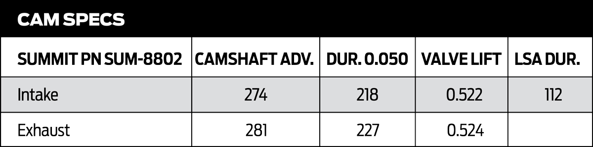
For our small-block, we originally used a mild street flat tappet cam with duration numbers of 214 degrees at 0.050-inch tappet lift. This produced valve lift numbers of 0.444 inch for the intake and 0.466 inch of lift on the exhaust based on the stock small-block 1.5:1 rocker ratio.
The hydraulic roller cam we chose to replace this flat tappet cam offers similar duration numbers as seen in the accompanying chart with 218/227 degrees of duration at 0.050-inch tappet lift for the intake and exhaust, respectively. But note that the valve lift numbers (again based on the 1.5:1 rocker ratio) have jumped to 0.522/0.524 inch. This is an impressive bump in valve lift of 0.78 inch on the intake side and 0.58 inch on the exhaust side.
These increases are because there is no mechanical limitation on the acceleration ramps on a roller lifter cam compared to a flat tappet cam. This allows the cam designer to create a much faster acceleration ramp for the roller lifter for the same amount of duration. This immediately creates greater potential power gains with a roller cam. This is especially true for engines with a better-than-average set of cylinder heads. Our budget small-block is fitted with a set of Summit Vortec heads that will accommodate the additional lift with no problem. So, we’re anticipating a measurable bump in power with this hydraulic roller cam upgrade.
If you’re still unsure as to whether a roller cam is in your future, consider that any flat tappet cam will require custom oil for the life of the engine. A performance flat tappet cam will demand a typical hot rod oil like Summit’s ZDDP-enhanced 10W-30 or 10W-40 oil. This is a built-in additional cost every time the engine needs an oil change. Hydraulic roller cam engines don’t necessarily need this ZDDP-enhanced oil and can use a slightly less expensive, off-the-shelf engine oil of the same viscosity.
Now that we’ve covered the relative advantages, let’s get into exactly how to convert from a flat tappet to a hydraulic roller. If the engine is in the car, in most cases it will probably be easier to remove the engine from the car unless there’s enough room for the cam to clear the vehicle’s grille assembly. Our conversion will be done on our Summit Racing engine test stand, so all we had to do was drain the coolant and pull the radiator from the stand. Then we unbolted the water pump and removed the harmonic balancer.
We won’t detail the disassembly since that’s a fairly typical effort. Once the intake and the rocker arms, pushrod, and lifters are removed, we removed all the oil pan bolts except the rearmost ones on each side to lower the oil pan enough to remove the front timing chain cover. With that accomplished, we then removed the timing chain set and the old cam.
We used a locking three-jaw puller to remove the crank timing gear and then used our harmonic balancer tool to press the new timing gear in place. The stepped-nose hydraulic roller cams use a different cam bolt pattern compared to the more traditional flat-nose Chevy cams, so it requires its own specific cam gear. The Cloyes crank gear has three different keyways with one for straight up, and one each for 2 degrees of advance or retard. We installed the crank gear in the straight-up position since our new cam is ground with built-in advance. With the crank gear in place, we installed the cam and then merely lined up the marks on the gear.
As mentioned earlier, these one-piece rear main seal engines use a two-bolt, flat steel plate to limit forward cam movement in the block. What is not commonly known is that there are two versions of this cam limiter plate with either a narrow or a wide bolt pattern. The narrow bolt pattern measures 3.294 inches while the second-generation plate is 3.620 inches. Our particular engine is a later model Gen II that uses the wider plate. Both plates are still available. We’ve included both GM part numbers in our parts list, although only one is required for any engine.
The Summit kit that we ordered that includes the spider and lifter retainer dog bones comes with the narrower Gen 1 limiter plate. It’s also important to note that Chevy uses a pair of round-headed Torx-style bolts to attach the limiter plate to the block. These are necessary to clear a performance timing chain set because regular hex-head ¼-inch bolt heads may be too tall.
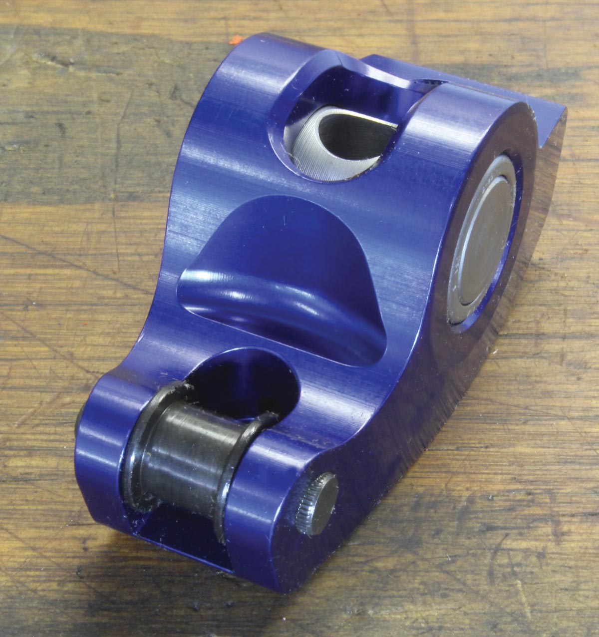
With that part of the install handled, it was time to address the cylinder heads. The original flat tappet valvesprings on our engine were way too mild to work with our hydraulic roller cam’s additional lift so we upgraded to a set of what are essentially LS6 beehive valvesprings that offer multiple advantages. First, these springs will offer more clearance to the valveguide seals so we don’t have to worry about smashing the seals when the retainer gets too close because of the greater valve lift. Plus, the reduced size of these beehive retainers improves stability at higher engine speeds. We also ordered new 7-degree, 11/32-inch valve locks, although it appears the original locks may, in fact, work with the beehive retainers.
The spring swap went pretty quickly. We used compressed air to keep the valve closed and quickly changed the springs using a Moroso over-center valvespring compressor tool. The rest of the conversion went rather quickly. We put thread-locking compound on all three cam gear bolts, torqued them in place, lubed the chain, and installed the front cover and oil pan. With the harmonic balancer in place and the water pump back on we were ready to install the intake manifold.
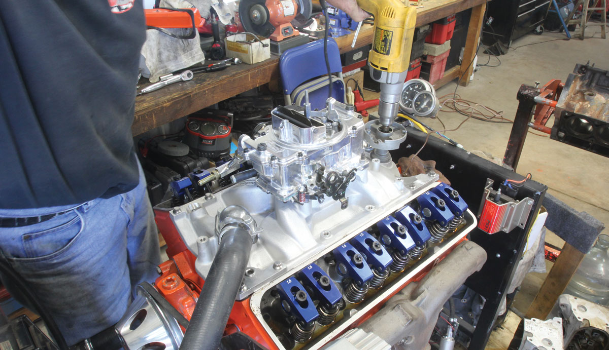
We prefer to set valve preload before we install the intake manifold so that we can double-check zero preload on the lifters and make sure everything is installed properly. Because our rubber Vortec intake gaskets were near new we didn’t have to replace them. With a nice new bead of RTV for the end seals, the intake slipped right into place.
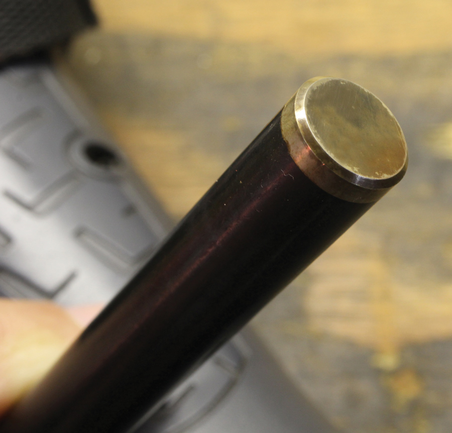
With this new steel roller cam, we also had to replace the original distributor gear. Steel cam gears do not mesh well with iron distributor gears and can be quickly worn so it’s critical to install a new melonized distributor gear. Melonizing is a heat treatment process that allows the distributor gear to wear properly with the steel cam gear. In fact, a melonized gear is compatible with any camshaft regardless of material.
If the engine will be run with a mechanical fuel pump and because this is a steel camshaft, this will also require a bronze-tipped fuel pump pushrod. We’ve included a part number for a Comp Cams pushrod that will prevent damage to the cam.
Before dropping the distributor in, we took the time to pressure lube the engine to make sure we had plenty of lube up to all 16 rocker arms. We lubed the new distributor gear and placed the distributor at 15 degrees before top dead center (BTDC) and plugged in all the rest of the spark plugs and wires. We then pre-filled the carburetor float bowls and primed the engine with several shots of fuel.
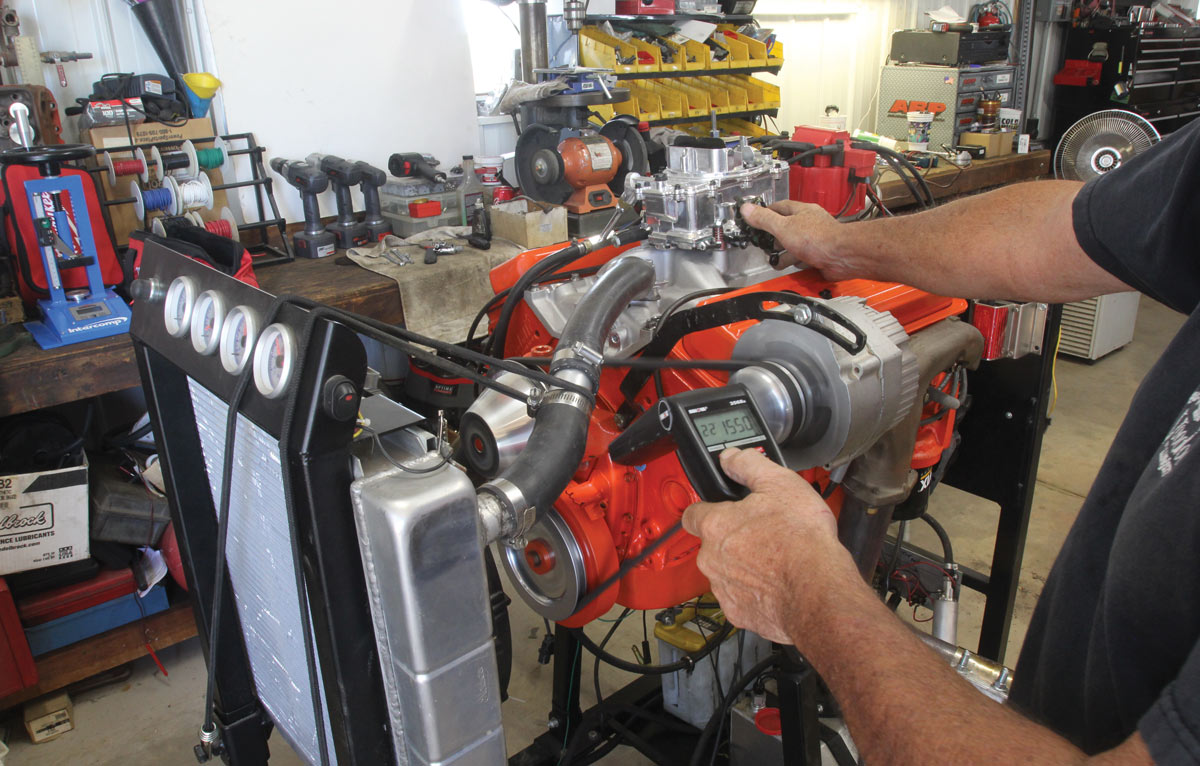
This ensured that the engine would start almost immediately, which it did. We ran the engine for a couple of minutes at around 1,600 rpm to ensure plenty of splash lube on the cam and lifters and then rechecked the timing and locked it down at 15 degrees BTDC for a total of 36 degrees of mechanical advance.
We’re now ready to drop this new engine into its new home in our ’65 El Camino with a nice new hydraulic roller cam that should make a little bit more power as well as being more durable.
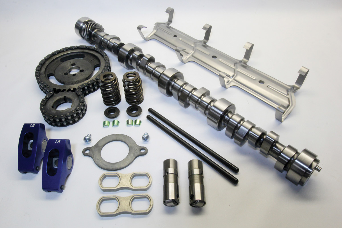
1. It does require a few parts to complete a hydraulic roller cam conversion beyond just the cam and lifters. We opted to upgrade the valvesprings to a set of LS6-style beehives along with guided roller rockers mainly because stock stamped-steel rocker arms do not offer sufficient slot travel to accommodate 0.550 inch of valve lift


5. With plenty of assembly lube on the journals, lobes, and distributor drive gear we slid the new Summit hydraulic roller cam in place.
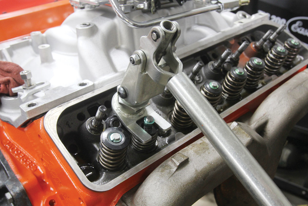
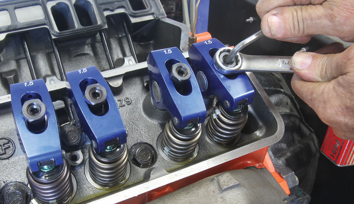
11. With the pushrods and the rocker arms in place, we set lifter preload at just a touch over a quarter turn and used the exhaust-opening/intake-closing method to set the preload.
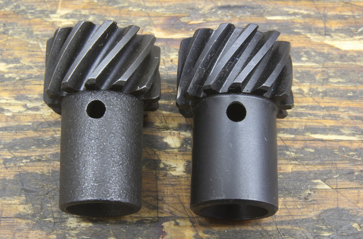
12. Many roller cams are now using a steel core. This requires a melonized distributor gear (left) to ensure it is compatible with the cam material. If you are not sure of the distributor gear material, an iron gear will have a smoother look to the lower portion (right) while the melonized gear features a mottled look. A stock iron gear used on a steel cam will quickly damage the distributor drive gear on the cam. It’s also a good idea to always use a new distributor gear with a new cam.
 SOURCE