ACP department heading TECH

InTheGarageMedia.com

Fueling Up title image
Installing a High-Performance Fuel System on a Gen V LT-Swapped ’68 Camaro

BY Evan Perkins Photography by The Author

W

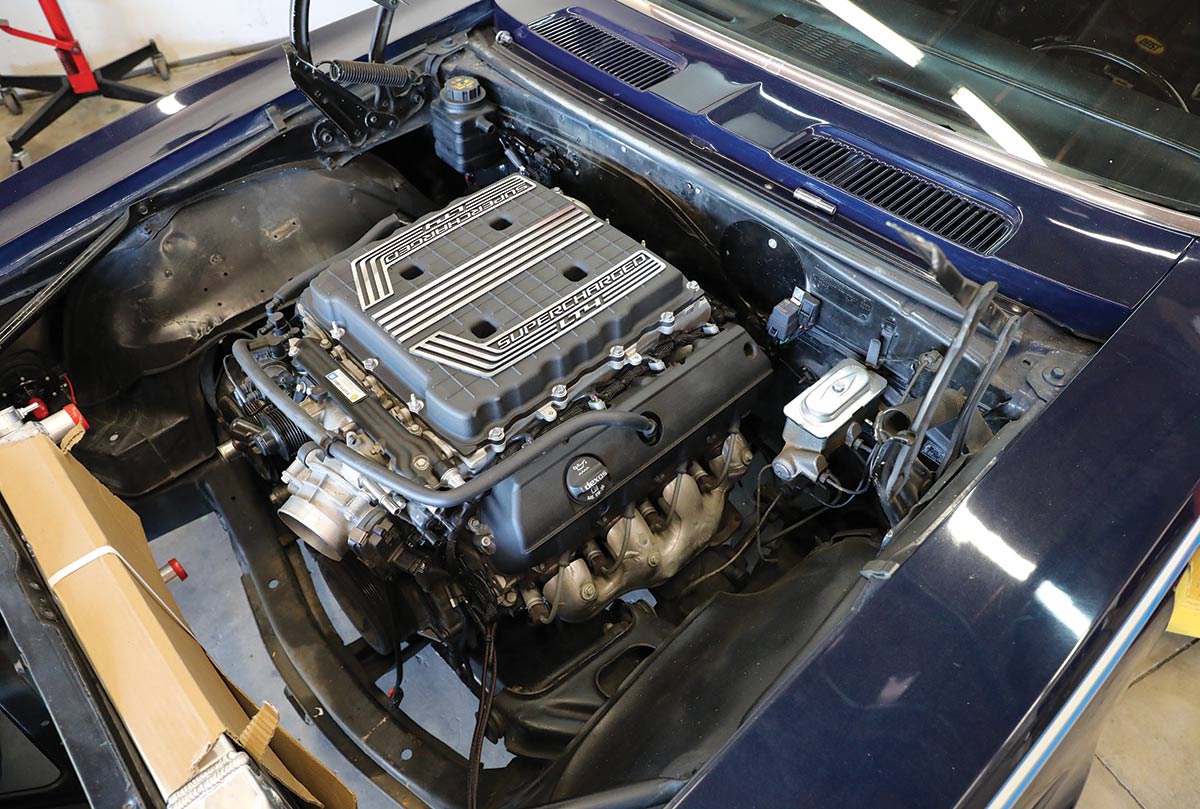
hen Chevrolet’s Gen V engine hit the market, it was a radical change for GM V-8 enthusiasts. The pushrods were still present, the cylinder heads were aluminum and reminiscent of the outgoing LS generation, but the fuel injectors were in a radically different place. Rather than incorporate the muti-port fuel injection that had long been the industry standard, for the Gen V (LT-based) engines, GM chose to add high-tech direct-port injection.

This new style of fuel delivery placed the fuel injector outlet directly in the combustion chamber. The effect is much more control over fuel per cylinder with a host of other efficiencies. However, for the hot rodder, it seemed, well, intimidating as these new systems require extremely high fuel pressures, upwards of 2,000 psi. This is accomplished in OEM vehicles by using an in-tank electric pump paired with a mechanical pump driven off the camshaft.

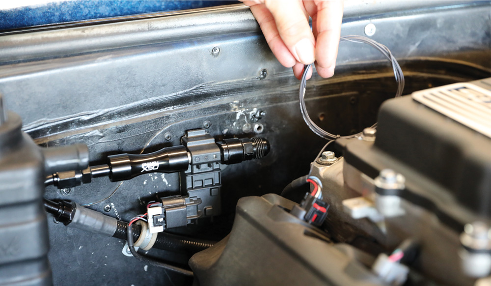
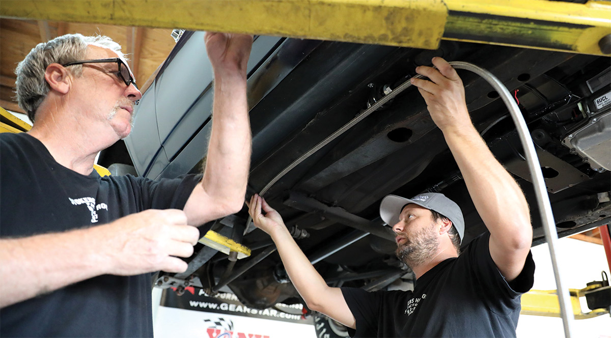
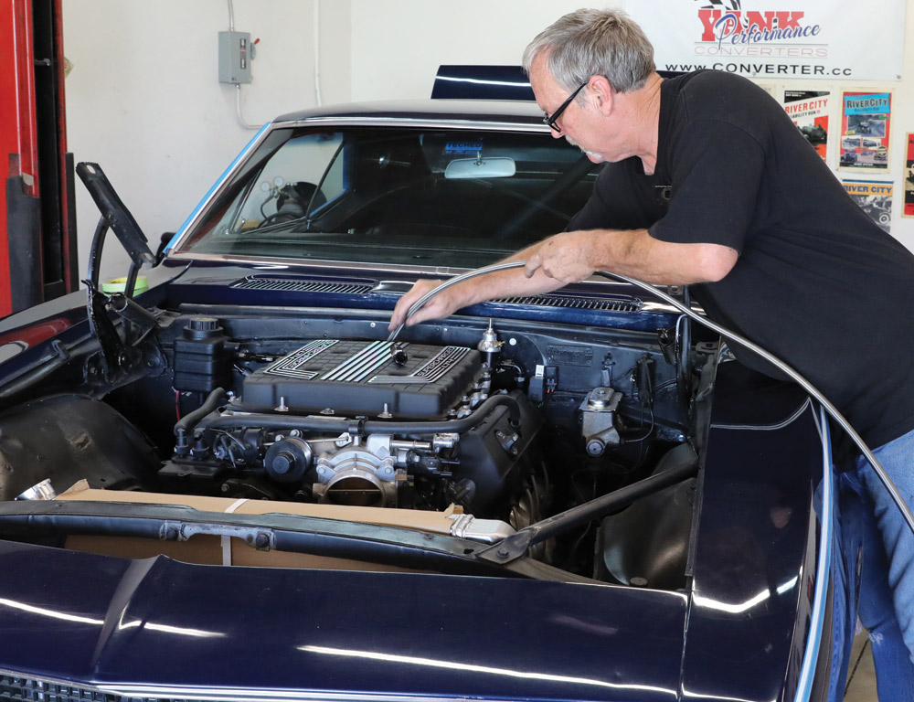
When swapping an LT into a classic vehicle, such as this ’68 ex-Super Stock Camaro being built at Stoker’s Hot Rod Factory, in Upland, California, the mechanical fuel pump is retained in the engine and only a new low-pressure side needs to be retrofitted.

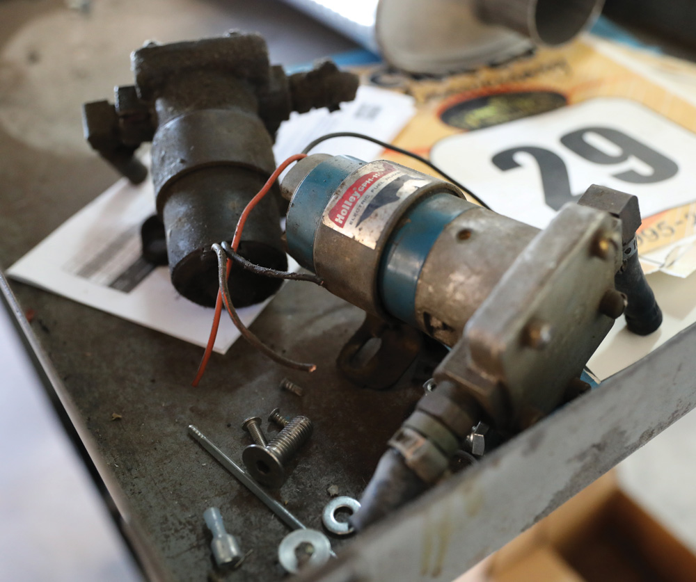
The OEM electric fuel pump on Gen V engines utilizes something called pulse width modulation (PWM), where the computer manipulates the fuel pump’s electrical current supply in order to speed it up or slow it down in relation to engine load. While it is possible to replicate a similar system with a PWM pump, the easiest way to accomplish the swap is to ditch the PWM pump and install a conventional electronic fuel pump with a return-style regulator.

However, it is important to note that the Gen V engines require a comparably high fuel pressure of 72 psi, which means not all pumps will be up to the task of delivering enough fuel. It’s also important to note that this 72 psi needs to occur at a relatively high 45 gallons per hour (GPH). That can place a lot of load on certain fuel pumps and shorten their service life. In Gen V applications, pump selection is more critical than ever before.

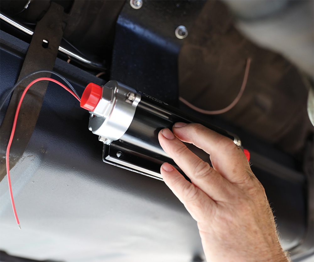
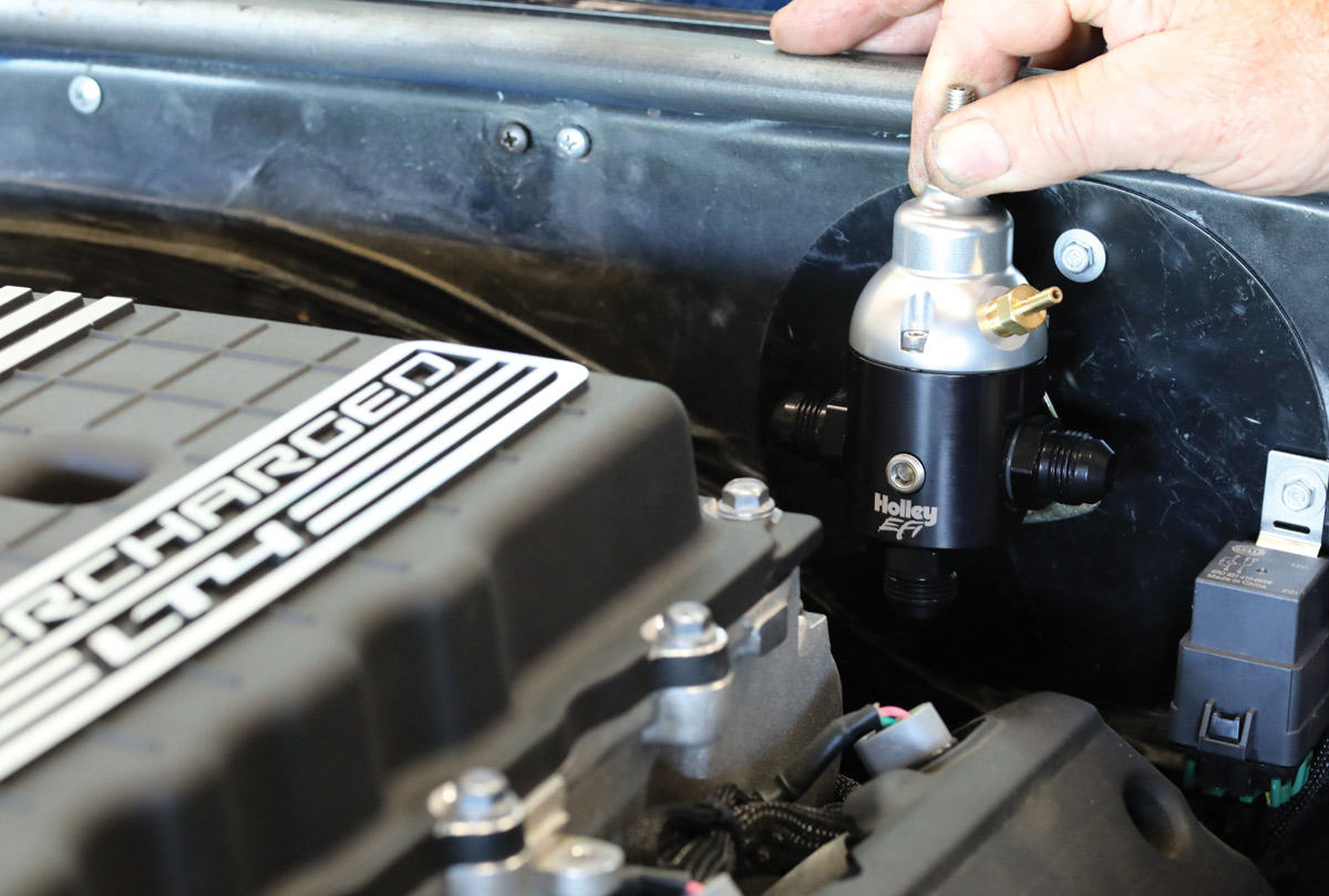
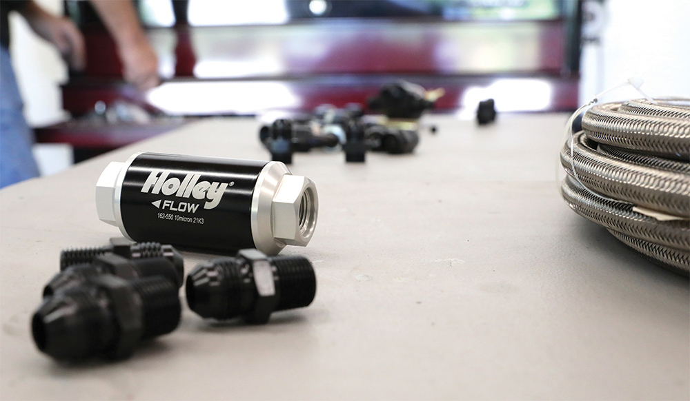
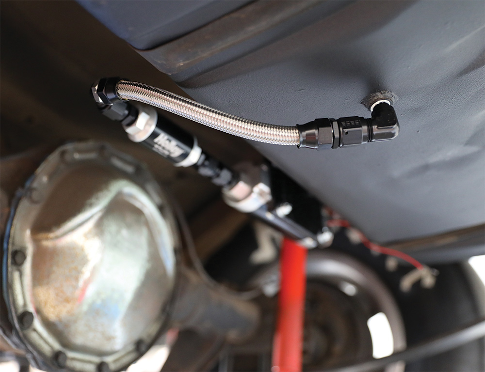
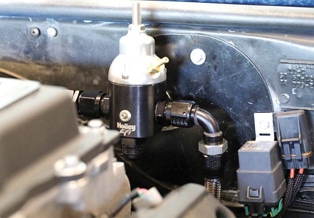
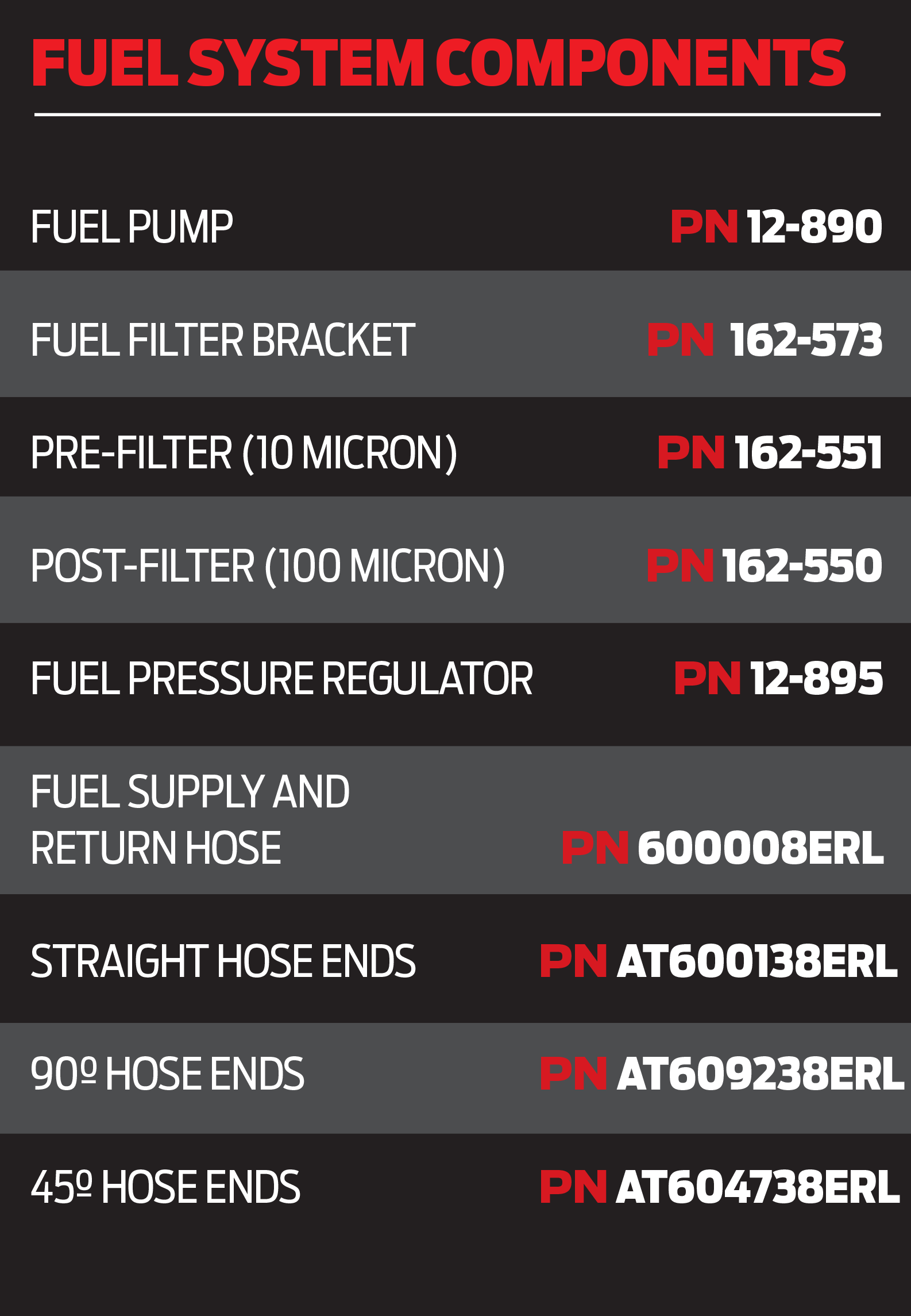
For the Camaro project being built at Stoker’s Hot Rod Factory and its Gen V–based engine, the pump of choice was a Holley Dominator (PN 12-890). The pump will be coupled with a return-style fuel pressure regulator (PN 12-895), which is adjustable from 15-90 psi.

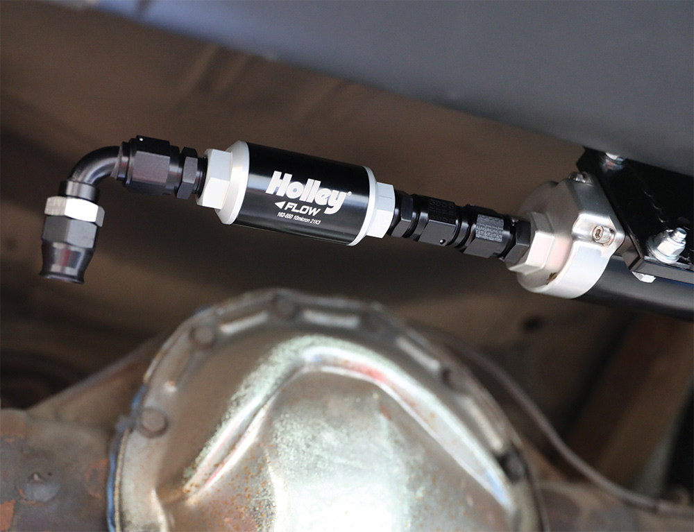
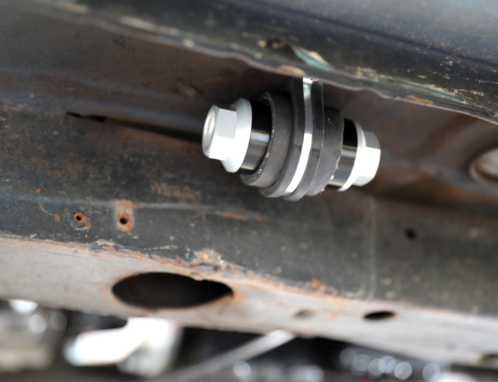
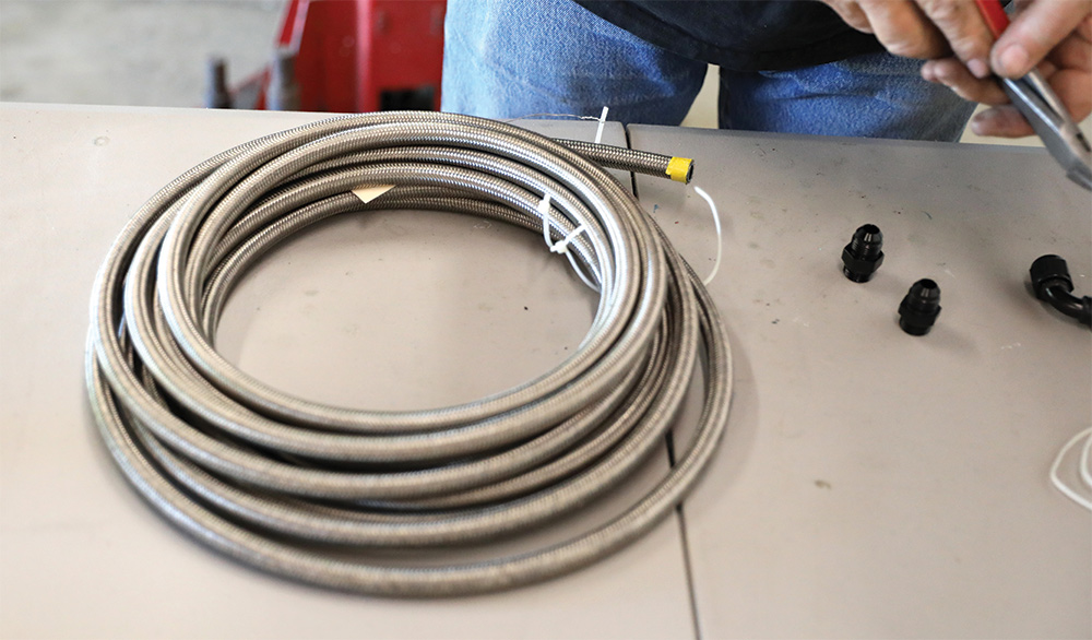
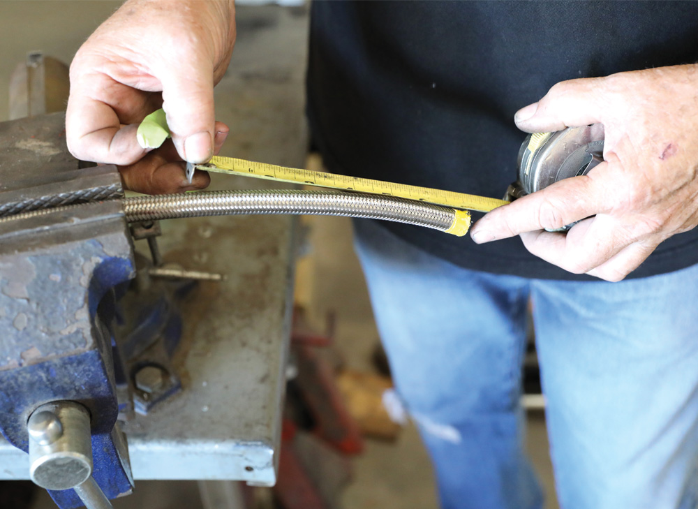
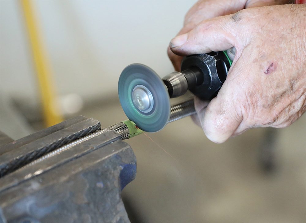
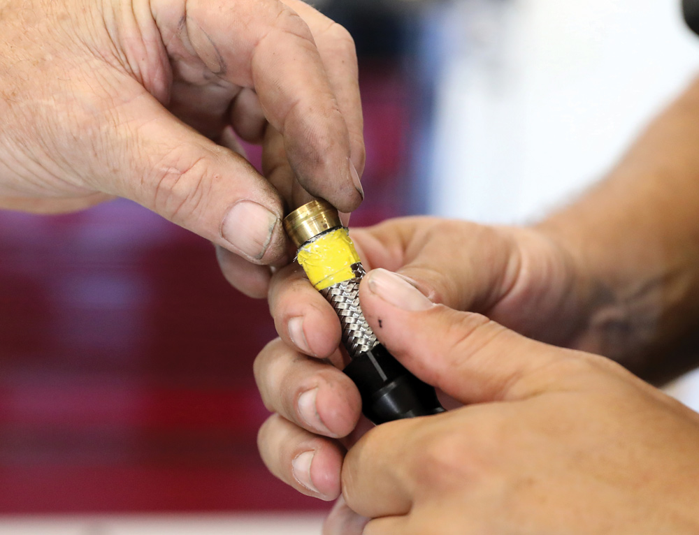
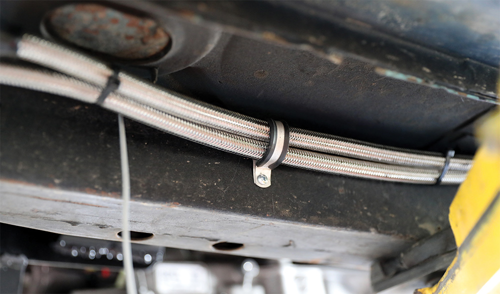
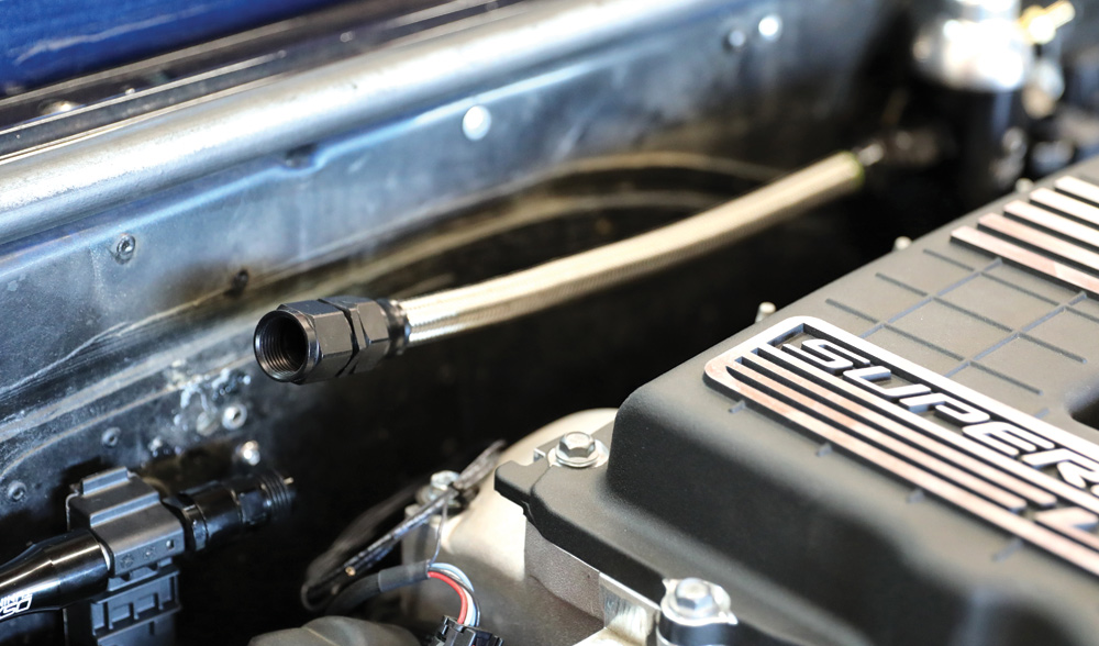
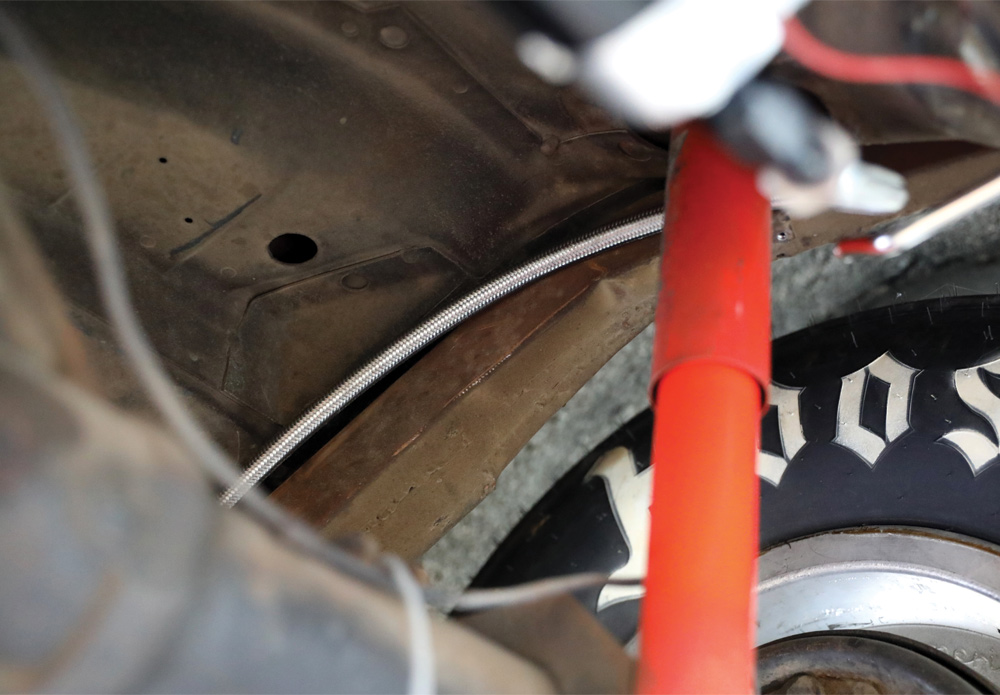
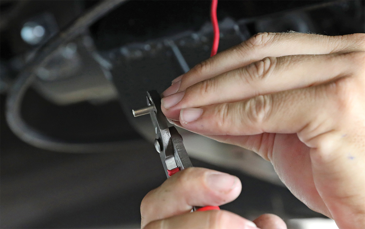
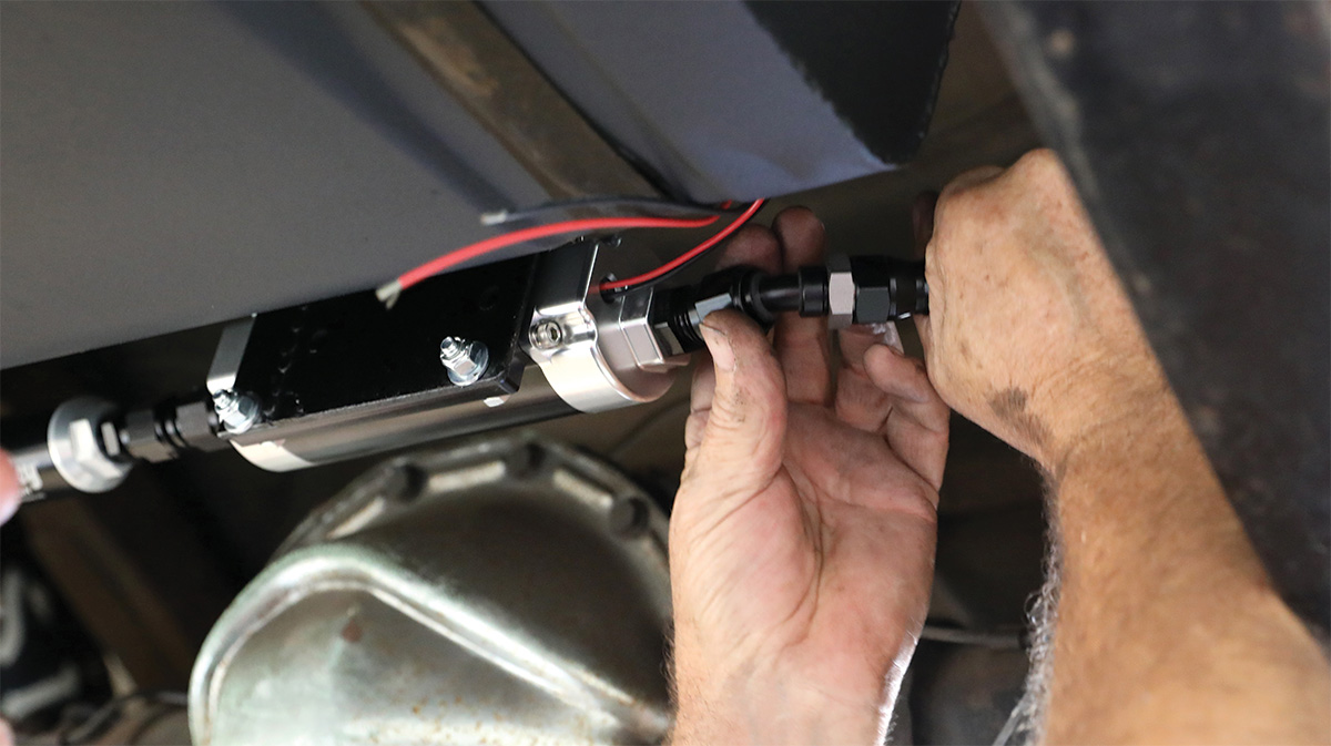
Follow along as Stoker’s installs the new fuel system, linking all the major parts and players to the engine with Earl’s AN fittings and braided hose.

Holley Dominator inline pump mounted near gas tank
1. The Holley Dominator inline pump is mounted on a bracket just in front of the fuel tank. Holley also offers in-tank pumps that run cooler and quieter, but for ease of installation, serviceability, and to preserve the period-correct fuel tank (which was already narrowed for tire clearance) this was the way to go.
Dual Holley blue pumps previously used on car
2. These twin Holley blue pumps provided fueling for the Camaro in its early life as an NHRA Super Stock racer.
Test placement of new fuel pressure regulator behind engine
3. Terry Stoker selects a spot behind the engine to mount the return-style fuel pressure regulator.
View of new LT4 swap in engine bay
4. The engine is an LT1 with a supercharger donated by an LT4. It will deliver a healthy amount of power (well over 600 hp) and have perfect driveability—something the mill’s former Super Stock spec engine would have marveled at.
Holley fuel filters
5. Having the correct fuel filters both before and after the fuel pump are key. This Holley unit (PN 162-550) filters to 10 microns while a finer 100-micron unit will be placed before the injectors to prevent them from getting clogged.
Ethanol content sensor
6. Shown is an ethanol content sensor. It is plumbed in line with the fuel injector rails (after the fuel pressure regulator) and provides a signal to the factory LT computer of how much ethanol is in the fuel. This will allow the engine to run on ethanol, gasoline, or a mix of both.
First fuel filtered mounted
7. The first fuel filter is mounted in between the fuel tank pickup and the fuel pump. This filter protects the pump from tank debris while not inhibiting flow. Too fine a filter before the pump will cause it to fail.
Second finer fuel filter mounted
8. The “finer” fuel filter is rated at 100 microns, mounted on the framerail, and will help protect the precision direct injectors from becoming clogged by debris.
Earl's Speed Flex fuel line
9. The braided fuel line selected for both the supply and return sides of the fuel system is Earl’s Speed Flex (PN 600008ER). Speed Flex is PTFE-lined for compatibility with all fuel types and assembles using Speed Seal fittings.
Terry begins the process of connecting all the components of the fuel system by measuring each length of hose. He wraps the areas to be cut in electrical tape to prevent the braided strands from fraying, then makes a clean slice with a cut-off wheel.
Cutting fuel lines to length with cut-off wheel
10-11. Terry begins the process of connecting all the components of the fuel system by measuring each length of hose. He wraps the areas to be cut in electrical tape to prevent the braided strands from fraying, then makes a clean slice with a cut-off wheel.
Installing Speed Seal fittings to Speed Flex hose
12. Speed Seal fittings use an “olive” or ferrule to seal to the Speed Flex hose. Terry slid the hose socket over the hose then inserted the olive in-between the PTFE tubing and braided steel strands.
Measuring length of fuel line
Cutting fuel lines to length with cut-off wheel
13-14. Next the fitting and fitting socket are pushed together and tightened until hand tight.
Mocking up fuel lines under chassis
15. David (right) and Terry (left) Stoker mock-up the Speed Flex hose under the car, marking cut points.
Adel clamps used to mount fuel lines
16. Adel clamps are used to mount both the supply and return fuel lines to the framerail. Zip ties hold both lines together to keep them from moving around too much.
Line linking regulator outlet side to ethanol sensor
17. This line links the outlet side of the regulator to the ethanol content sensor.
Fuel tank pickup flowing into prefilter
18. The fuel tank pickup flows directly into the 10-micron pre-filter for the Holley Dominator pump.
Pulling fuel lines through engine bay
19. Terry fishes the Speed Flex Earl’s hose through the engine bay to accurately measure the final length.
Installed regulator
20. The 45-degree bent-tube fitting on the right of the regulator is the supply line from the pump. The -8 fitting on the bottom is the return side to the tank.
Fuel line routed over rear axle
21. The fuel line is carefully routed along the framerail where it swoops over the rear axle.
Running power to pump
22. David runs the power wire to the Dominator pump.
Connecting pump to supply line
23. Lastly, once all the other hoses and fittings have been cut, installed, and tightened, Terry connects the pump to the line that will supply the engine.
List of used fuel components
Holley
(866) 464-6553
holley.com
Stoker’s Hot Rod Factory
(909) 920-6797