 TECH
TECH
 Images by the Author
tarter motors are kind of like the guy behind the counter at the auto parts store. When he’s competent and efficient you may not notice. But if he can’t find a stock spark plug for your 350 small-block 1969 Camaro, this attracts your attention and not in a good way. Starter motors can be like that—the only time you notice them is when they don’t work.
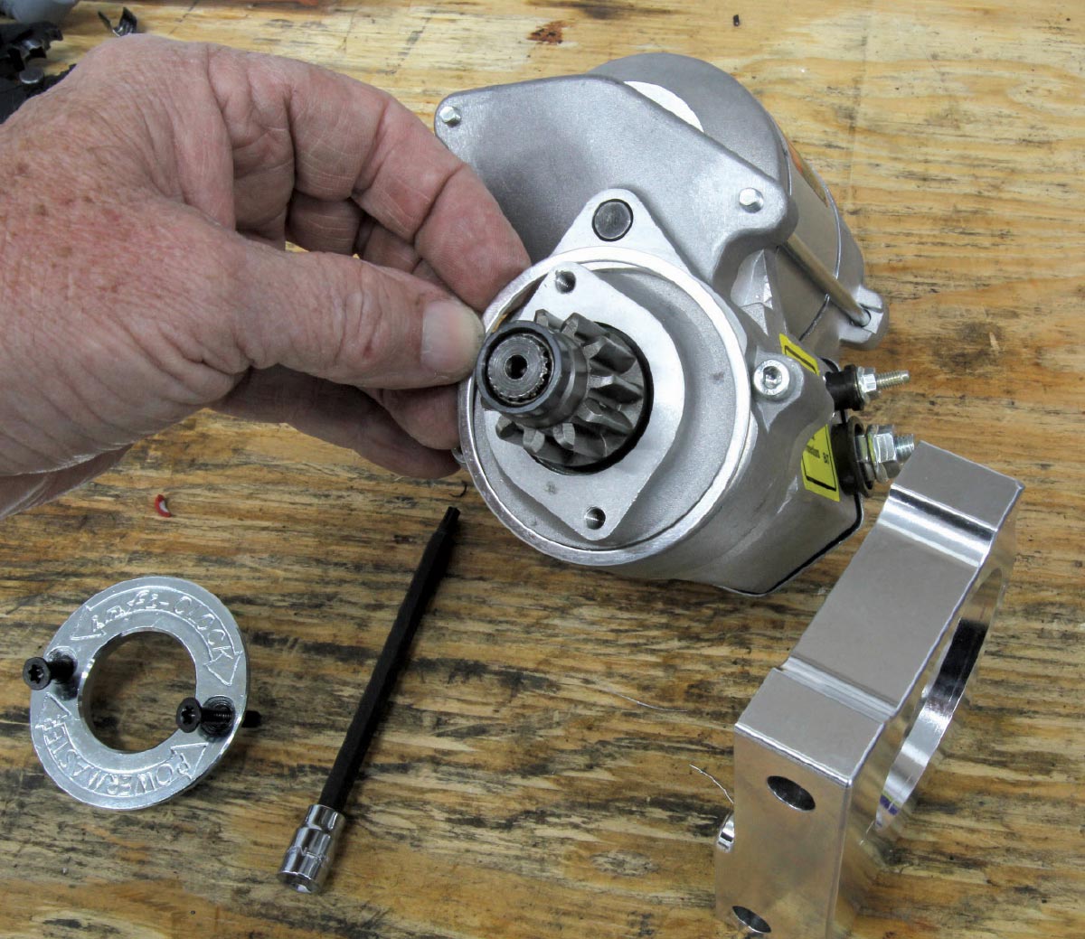
Starters don’t contribute to horsepower, so they are often overlooked—until they don’t do their job. Such was the case for a stout small-block we found ourselves working on recently that offered up more than a little irritability. The owner had recently purchased his XS-series Powermaster starter motor, but it wasn’t happy. The noise it made during cranking was approaching painful.
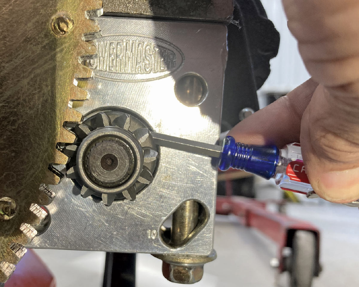
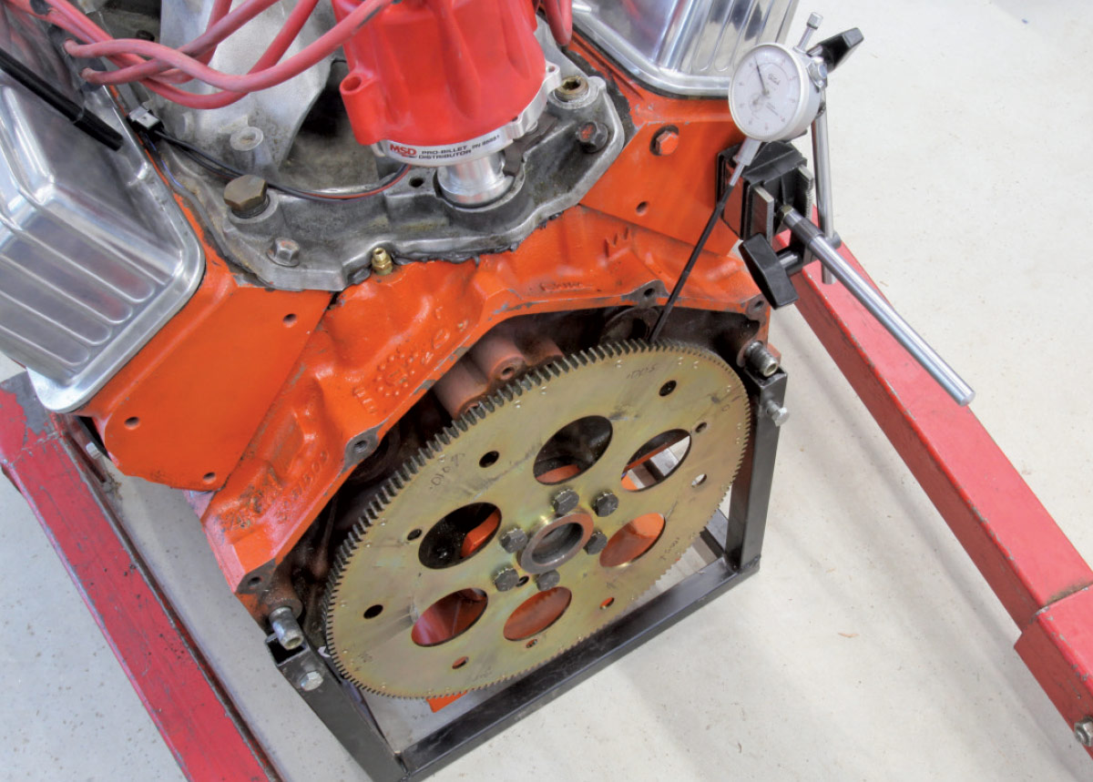
It was obvious something wasn’t right. First, we looked at the relationship of the starter pinion gear to the flexplate. With the engine out of the car, it was easy to measure the clearance between the pinion gear and the flexplate. The proper spec for gear clearance was supposed to be 0.040 inch, but our check revealed it to be in excess of 0.100 inch.
For most engines, starter motors are mounted so that the gear engages the flywheel below the horizontal crankshaft centerline. In order to tighten the gear clearance, this required moving the pinion gear upward. This particular starter used an aluminum adapter, so it became clear this adapter needed to be milled in order to bring the pinion gear closer to the crankshaft/flexplate centerline. This would reduce the excessive gear clearance.
We opted to machine 0.050-inch off the top portion of the starter, which immediately improved the clearance between the gears to almost exactly the 0.040-inch spec.
After careful inspection we also discovered that the long starter bolts that were used for this starter were not the bolts supplied with the Powermaster starter motor. The ones in use actually bottomed out in the block by roughly 0.050 inch before securing the starter to the block. Adding a thick washer between the bolt head and the starter block would have been a simple solution but instead we trimmed the bolts shorter, which eliminated the need for the washers and also the possibility of the bolts being used at some later date without the washers. With these two repairs, the starter now spun the engine over easily and was dramatically quieter.
If the starter gear had suffered from too tight a clearance, the fix would have been much simpler as all we would have to do is add a shim between the starter and the block to move the pinion away from the flywheel to increase the gear clearance.

During this evaluation, we also measured the lateral runout of the flexplate at the end of the gear teeth and found it to be within 0.012 inch. We found specs for a high-quality billet flexplate from Meziere Industries listing 0.005 inch, so our stamped flexplate with slightly more lateral runout could be considered acceptable. Fore-aft runout on the ring gear face was less than 0.007 inch and also within spec.
Now that we’ve covered the mechanical side of the starter motor, we can move to the electrical side. Old-school starters from the ’60s employed heavy and large field coil magnets to produce direct drive starter motor torque. While these units did their job they are also inefficient and ridiculously heavy.
Modern starter motors are much smaller and use permanent magnets that are more efficient motor operation. But the main reason these units are designed smaller is because nearly all enjoy the benefits of a planetary gear reduction system. Much like similar gearsets in an automatic transmission, the starter motor inputs torque into the planetary system, which then multiplies the torque output. This planetary gear reduction system multiplies the starter motor torque by a factor of anywhere from 3.25:1 to over 5:1, depending upon the brand and model of the starter.
These smaller OE permanent magnet starter motors really do a great job for stock and mild production engines, but we’ve learned through experience that using OE starters on large-displacement or high-compression engines often ends with a failed starter drive. The outer ring gear on the planetary system on these OE starters is plastic that quickly fails under higher load requirements.
Aftermarket starters like those from Powermaster, Tuff Stuff, Meziere, and others identified this problem and now incorporate steel gears in their planetary geardrives that eliminate this issue. Another way to improve the starter motor’s torque multiplication for small-block Chevys is to step up to a larger 168-tooth flywheel or flexplate. This larger diameter improves the overall torque multiplication compared to the smaller 153-tooth version.
Keep in mind that for the small-block Chevy the smaller flexplate or flywheel is always paired with the straight-across starter mounting bolt pattern while the larger flexplates and flywheels employ the offset bolt pattern. Some starters with adapter blocks offer a dual bolt pattern on the straight-across style that will accommodate either diameter flywheel or flexplate. This isn’t an issue with LS engines since they all are designed to use only the larger 168-tooth diameter.
Next on the list of enhancing the starter’s ability to spin the engine more efficiently is to ensure the battery can supply sufficient electrical power. First check that the battery is in good condition with a resting voltage of 12.6 V or higher and the terminals are clean and tight. Next, larger-diameter battery cables will always deliver more power by minimizing electrical resistance. An optimal cable size for most starter motors would be either a 1/0- or 2/0-wire gauge available through multiple sources.
If you suspect that your starter motor’s cabling might be marginal, there is a simple voltage drop test you can perform that measures the cable’s performance while under load. All you need is a digital voltmeter and a friend to turn the ignition key.
First make sure the vehicle’s transmission is in Park with an automatic or in Neutral if it’s a manual transmission. Disable the ignition so the engine won’t start. We will describe this test for the negative battery cable because the connections are easier to access. The test procedure is exactly the same for the positive battery cable.
Configure the digital gauge to measure voltage and place the positive probe on the battery terminal and the negative probe on the engine’s ground connection. Now have a friend crank the starter motor, making sure your hands are clear of the accessory drive. Never crank the starter motor for more than 5 to 10 seconds at a time and allow several minutes in between tests to allow the starter to cool down.
As soon as cranking begins, the meter will display a voltage reading. This voltage is directly related to the resistance in the cable system. A solid connection with a quality cable should indicate less than 0.50 V and ideally around 0.025 V. This voltage reading actually indicates resistance in the circuit. Higher voltage readings indicate the cable is using more voltage to overcome resistance.
Adding the voltage drop test results of both the positive and negative cables should equal no more than 0.50 to 0.75 V for an optimized cranking system. If you suspect your starter is underperforming this is a great place to start eliminating variables in the system. If the battery cables reveal acceptable results then you know the problem is elsewhere.
We’ve seen brand-new budget battery cables that could not pass this test, so don’t be fooled just because the cables are new. This is an especially good test for cars where the battery is in the trunk as long cabling can cause excessive voltage drop. Keep in mind that with longer cables, the acceptable voltage drop numbers could be slightly higher.
Another circuit worth testing is to verify that the cranking voltage at the battery cable post on the solenoid. During cranking, the voltage should be no less than 11.0 V. Another circuit that is rarely tested is the voltage supply at the solenoid from the ignition switch. Older vehicles are often susceptible to voltage losses through this circuit.
This solenoid trigger voltage should be similar to the cranking voltage at the battery cable connection. If the voltage is lower, it’s possible the solenoid may not perform as intended, creating that familiar clicking sound often associated with a bad starter. If the solenoid feed wire (the famous purple wire in older Chevys) is supplying insufficient voltage, this could be a cause for starting difficulties.
In this short piece, we’ve covered both the mechanical and electrical sides of the starter circuit. Engine starting difficulties can usually be traced to one or both of these areas. Starting a performance engine shouldn’t be difficult and once you’ve verified these areas for proper performance, you can return to the ever-present question of figuring out how to make your engine run better with the knowledge that at least it will always start!


 SOURCES