 Photography by The Author and Courtesy of the Manufacturers
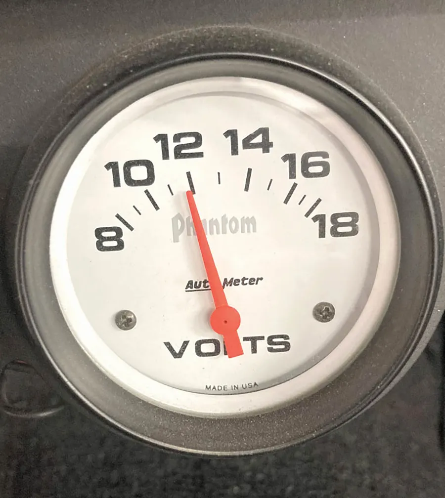
t’s a common scenario. You’ve just added a larger radiator with a pair of performance electric fans to help cool that hot small-block. Everything is working great until you take your Camaro out for an evening cruise at the local hangout. That’s when you notice that at idle with the headlights on and both fans running the voltmeter is sitting on 11.5 V instead of the 14 it used to read at idle. Plus, the headlights get brighter when you rev the engine. Something is amiss.
In the early days of muscle cars, alternator output was in the range of 40 to 60 amps. There just weren’t that many electrical accessories that required more than perhaps 30 amps. But today, we have a ton of electrical components that place an increasing demand on the charging system. Today’s new vehicles are commonly equipped with 140- to 160-amp alternators. The same is true for modern muscle cars running items like electric fans, a high-pressure fuel pump, A/C, electric vacuum pump for power brakes, heated and cooled seats, and a host of other amenities.
While individually these different electrical options pull only a minor amount of amperage, it’s when you add all these items up that the issue becomes clear. So instead of a tiny 60-amp alternator, you might be looking at over 100 amps of charging capacity demand—at idle. This idle thing is the key. Alternators do not output maximum amperage at idle. Most require an engine speed of 2,000 to perhaps 3,000 rpm to approach maximum output. When evaluating alternator output, the key is the speed of the alternator itself.
We’ll get to that in a moment. But first we need to look more closely at alternator output rating. Powermaster was the first company we noticed that includes an output report with each alternator listing its amperage at idle, cruise, and maximum. It’s useful to understand that Powermaster tests these alternators at ambient temperature. With older alternators, operating temperatures of 150 degrees F or higher, these specs will drop by roughly 20 percent. So, at idle, a 100-amp rating will likely be closer to 80 to 85 amps.
When we recently posed this question to Powermaster’s Todd Ryden, he told us that modern winding designs are much more efficient at idle so that efficiency number is better but that there could be up to a 20 percent loss at maximum output. But with alternators now capable of 250 amps, even a 20 percent loss at maximum could still produce roughly 200 amps, which should feed even the most voracious electrical load.
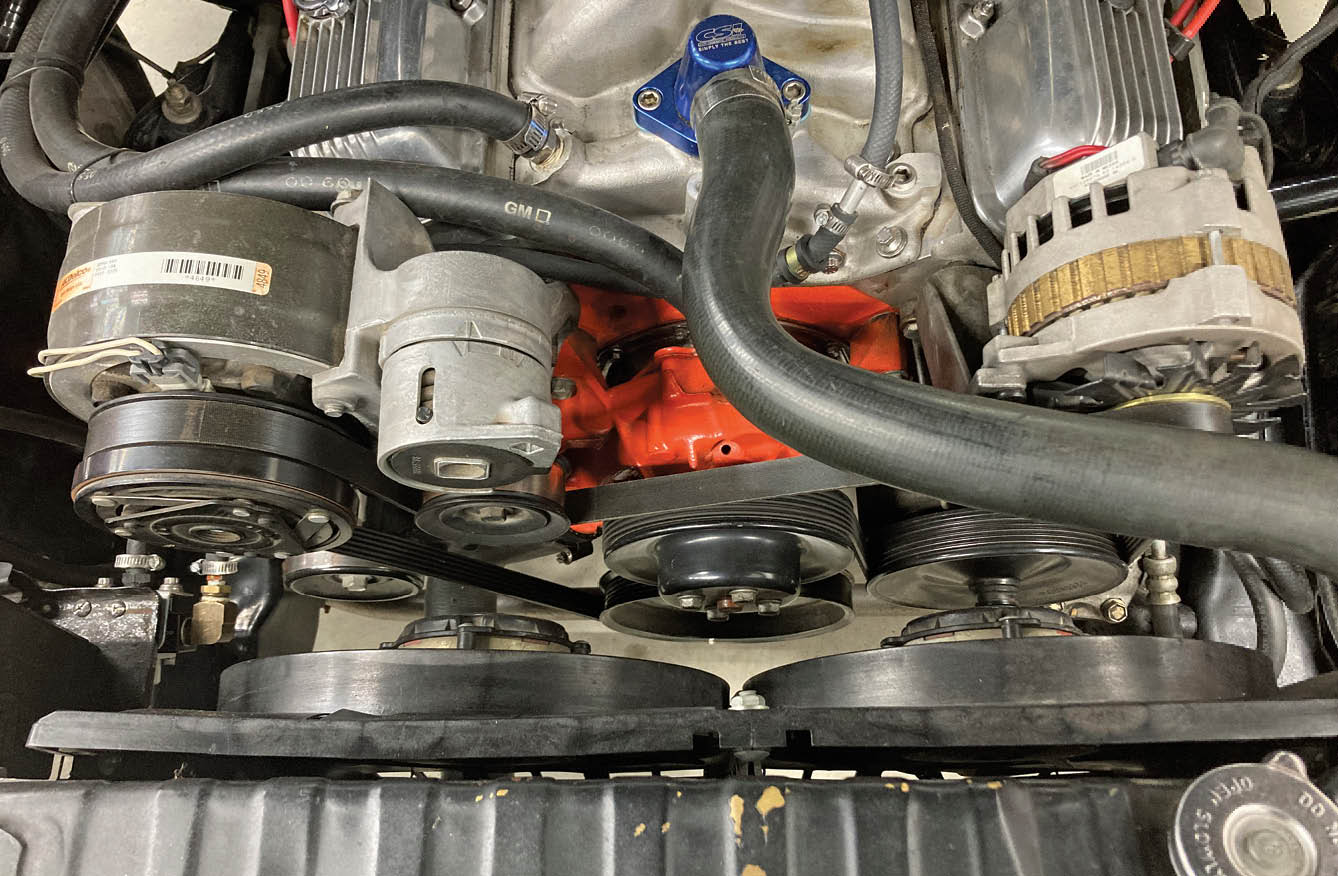
As we mentioned earlier, alternators are least efficient at slow speeds. Most charging system recommendations point to a 2.5 to 3:1 drive ratio for their alternators. This means that the crankshaft drive pulley should be roughly 2.5 to 3 times larger than the alternator pulley. So, a 6 ¾-inch crankshaft pulley would work well with a 2¼-inch alternator pulley.
This higher ratio improves output but also spins the alternator faster at higher engine speeds. So, if you plan to spin the engine above 6,500 rpm it’s best to reduce the ratio to prevent over-revving the alternator. Most alternator companies prefer to see the alternator speeds below 15,000 to perhaps as high as 18,000 rpm.
Alternator companies like Powermaster and others are now touting something called Hair Pin Replacement (HPR) technology. This refers to the use of custom-wound alternators using a special square wire that allows packing more windings into a small-frame alternator to produce higher output.
One example of HPR would be Powermaster’s small-frame alternator (PN 85296-1) that will bolt in place of the GM 10N, 10Si, or CS130 alternators but is rated at 145 amps at idle and 175 amps at full output. Of course, with denser copper windings, this means the alternator must cost more, in the mid-$300 range, but offer the ability to crank out big amps when called upon.
Over the years, GM has consistently upgraded their alternators so there are plenty of versions from which to choose. The oldest 10DN alternators used an external voltage regulator that was eventually internally integrated with the 10Si. This version was eventually upgraded to the CS130 in the late ’80s and early ’90s and remains one of the more popular swaps for muscle cars since the case allows it to be easily adapted to earlier accessory drives. Of course, many companies, including Tuff Stuff, also offer upgraded output versions of each of these designs should you desire to adhere to a specific case design.
Each of these different alternator designs use its own wiring plug in addition to the large output terminal on the end of the case. When upgrading from a 10Si, for example, to a CS130, there are wiring adapters that will make it a simple process to just plug the adapter harness in place and be ready to go.
Another option is one-wire alternators. These alternators are similar in every respect to their traditionally wired cousins, but the one-wire term means you simply connect the main output wire on the back of the alternator and it’s ready to run. These alternators rely on internal voltage to self-excite, which then begins the process of producing voltage and amperage.
This self-excite operation requires the alternator to spin at a certain rpm before it begins to crank out voltage and amperage. So, if you merely start the engine and allow it to idle, the low idle speed (and perhaps lower step-up ratio) is often not sufficient to begin the charging process. The trick is to merely rev the engine once above 2,000 to 2,500 rpm. This will self-excite the alternator to charge and maintain its output even at idle.
Beyond the alternator’s ability to produce sufficient output, there are other factors that can affect output. A very common application problem is an undersized main charge wire connecting the alternator to the battery. This is an issue especially with older cars where the alternator has been upgraded but retains the original charge wire. These OE charge wires were designed for systems that demanded perhaps 40 amps.
But now with electrical loads often exceeding 130 or more amps, these small wires are overloaded, creating excessive resistance. This can be the case even with normal electrical loads so it’s worthwhile to perform a test to evaluate how efficiently the alternator is charging the battery and the rest of the vehicle’s electrical system.
The test is extremely simple. All you need is a voltmeter. Set the meter to read voltage and start the engine and apply a modest load to the charging system by turning on the headlights and perhaps the blower fan on medium speed. First measure the voltage produced at the main output post on the alternator. For this discussion, let’s put the meter reading at 14.6 V.
Now with the engine running and no changes, record the voltage at the actual battery terminals. Place the voltmeter probes on the actual battery terminals instead of the connections. Again, for this discussion let’s say that the voltmeter reads 13.7 V. This means we have a loss of 0.90 V between the alternator and the battery. We can directly relate voltage drop to electrical resistance. Much of this drop is related to normal resistance that occurs anytime current is pushed through a conductor.
The common accepted voltage drop between the alternator and the battery is 0.4 to 0.5 V. So, in this example, it should be obvious that we could improve the amount of voltage and amperage delivered to the battery by improving this simple circuit. When adding a higher output alternator most companies recommend a larger charge wire to allow the alternator to do its job more efficiently.
Another test worth running is to do a voltage drop test on the ground side of the alternator. With the engine running, place one probe on the case of the alternator and the other on the ground post of the battery. If the voltmeter reads more than 0.25 V, this indicates there is excessive resistance on the ground side of the charging system. This usually means a poor ground between the alternator and the engine, missing ground straps between the engine and body, or perhaps an undersized or corroded battery ground cable.
Of course, you can begin the improvement process by simply cleaning the battery terminal connections and the charge wire connections. But if this does not improve the circuit’s performance, then a larger wire is needed. We’ve included a chart that offers recommendations for charge wire size based on alternator output as well as the length of the wire.
Adding a larger charge wire is especially critical with alternators capable of 150 amps or more. This is critical because the higher output current flow also produces more heat, so a larger conductor or charge wire is absolutely necessary. Common sense also dictates that if the battery is located in the trunk the charge wire will need to be substantially larger to minimize the voltage drop over the greater distance.
We’ve really only hit the high points of the world surrounding alternator and charging system performance but hopefully offered some ideas on how you can improve your vehicle’s electrical system so that it is more reliable and will keep all your electrical components happy for years to come.
The A/C blower fan is on medium, the headlights and brake lights are on, and the stereo is running on a medium volume. The total amp draw for this scenario is 90 amps, which pulls the operating voltage down to 11.5 V. Unfortunately, now the electric fan is operating well below its intended operating voltage of 13.5 V, which could contribute to an overheating problem. The good news is that this low voltage at idle can be improved with some simple charging system upgrades, including a higher output alternator, a higher pulley ratio, and a larger charge wire between the alternator and the battery.


PN 478601
SOURCE Summit Racing
Tuff Stuff CS130, 160-amp, natural
PN TFF-7935
SOURCE Summit Racing
Tuff Stuff CS130 105 amp, chrome
PN 7936D6G
SOURCE Summit Racing
Tuff Stuff pigtail 10Si to CS130D
PN TFF-7625A
SOURCE Summit Racing


 SOURCES