
Updating A Second-Gen Camaro Fuel System For LS Power
 Photography by The Author
ushing fuel is serious business. Regardless of whether you’re feeding a stock mill or looking to install a hopped-up LS packed with plenty of go-fast goods to make it breathe fire, having the right fuel system to handle the job is of the utmost importance. If you plan on running carburetion or fuel injection enhanced by turbos or a supercharger, it will add even more demands to the delivery process. It takes careful planning to supply the perfect balance of fuel to meet the needs of today’s high-performance engines, with each application having specific needs to reach its goals.
During a recent visit to Procision Industries in Taunton, Massachusetts, we met with shop owner Pat O’Brien who had recently wrapped up outfitting a fresh 5.3L LC9 LS for installation into his ’71 Camaro project car. With the engine sporting aluminum heads by C3 Automotive Machine, Stage II LS1 cam from Brian Tooley Racing, and an LS Classic Series by Lokar Classic 14-inch intake kit, incorporating a Holley single-plane EFI LS intake with matching fuel rails along with factory GM fuel injectors and Granatelli Motor Sports 103mm throttle body, it was a perfect opportunity for All Chevy Performance to follow along as O’Brien began mapping out a plan.
Starting in the engine bay, O’Brien first determined the need for specific fittings, fuel line type and length, and line clamps while moving rearward to decide on a regulator, fuel filter, fuel pump, and tank options. With many of the system parts available in kit form or individually, it’s easy to build to your custom application needs to handle a specific type of fuel delivery.
To illustrate the updating of a stock fuel tank to handle the EFI requirements of a modern LS, O’Brien contacted Summit Racing for one of their stock-replacement 20½-gallon steel fuel tanks. From there, Summit offers a perfect retrofit kit from Tanks Inc. with their PA-Series in-tank fuel pumps used to incorporate an internal fuel pump into an original gas tank. The EFI Tank Conversion Module kit comes complete, including a reservoir tray to eliminate fuel pump starvation, which is possible in non-baffled tanks, and a Walbro high-performance, high-flow fuel pump rated for up to 630 hp at 60 psi (ideal for this application with higher horsepower applications available). An OER fuel tank sending unit from Summit completed the tank build.
It’s important to note that a properly installed internal fuel pump will get rid of common issues often experienced with external fuel pumps, such as vapor lock and cavitation. Rounding out the system, Summit Racing supplied one of their Universal LS Fuel Filter/Regulator kits incorporating a Corvette-style, 58-psi rated fuel filter/regulator along with -6AN fittings.
Let’s follow along to check out in detail how the system is installed on this second-gen Camaro.

1. For a fresh start, the 20 ½-gallon steel fuel tank with silver powdercoating from Summit Racing was selected to act as the base for the new fuel system on the second-gen Camaro.

2. Summit Racing supplied the Tanks Inc. PA-Series in-tank fuel pump system to retrofit an internal fuel pump into a factory-style fuel tank. The EFI tank conversion module comes complete, as pictured, including reservoir tray and support arm, Walbro high-performance fuel pump, in-tank wiring harness, and all related installation hardware.

3. To prepare for installation of the in-tank fuel pump system, Pat O’Brien of Procision Industries reviewed the tank exterior for the best placement of the unit by test-fitting the OER tank sending unit with float first, followed by checking for any internal baffles.

4. Once the installation area was selected, O’Brien used the retainer ring gasket as a guide for the mounting plate. Using a marker, he then set the center point for the required 4½-inch-diameter mounting hole.


⅛ -inch pilot hole was drilled first followed by a ¼-inch hole. O’Brien then used a 4½-inch holesaw to finalize the opening to the tank. 


11. The slotted retainer ring was centered and secured in place using clamps on the tank followed by a punch used to mark the 16 mounting screw locations. A 3⁄16-inch bit was then used to drill the holes. Finally, the tank was vacuumed and blown clean of any debris.

12. Start the build of the pump module assembly by first measuring the depth of the tank to determine the support arms’ required length. For our application it was 6.25 inches.

13. The support arm was cut to fit using a band saw.

14. Assemble the support arm to the reservoir tray using the stainless steel #10-32 nut, washer, and bolt provided.

15. Apply Teflon tape to the provided 90-degree supply and return elbows with hose barbs. Dress threads with a dab of fuel-resistant gasket cement as lubricant and screw into the mounting plate. Finally, tighten with a ⅝ -inch wrench, being sure to have them in the desired final position.

16. Secure the foam sleeve and in-tank filter to the Walbro high-performance fuel pump.


18. Secure the supply line to the center barbed fitting with the supplied clamps and install the return tube over the remaining barbed fitting. Note that a heat gun might help with its installation.

19. Using the supplied wire ties, first install the large one through the previously installed black wire tie saddle and around the pump till secure, then trim excess. Follow by installing the small wire tie to secure the pump to the return line and trim excess.

20. Connect the in-tank wiring to your fuel pump and be sure the connection is secure. Follow by routing the wires through the pass-through fittings while allowing a bit of slack to avoid any chafing. Use a 9mm wrench to carefully tighten the upper jam nuts down on the wire with ¼-inch increments till the wiring is secure.

21. Slip the slotted mounting ring into the tank using the slot in the ring. Line up the mounting holes and secure in place with a couple of strips of masking tape.

22. Apply a liberal coating of fuel-resistant gasket cement to one side of the 16-hole mounting gasket and stick it to the underside of the mounting plate of the pump module. Then, carefully insert 15 ⅝ -inch screws and a 2-inch screw in the remaining hole.

23. With the pump module upside down, apply a coating of antiseize to the threads of each screw. Follow with a liberal coating of fuel-resistant gasket cement to the underside of the gasket to prepare it for installation.

24. Carefully insert the end of the tray into the tank opening and rotate the rest of the module downward and through the opening. Follow by starting the 2-inch screw into the mounting ring.

25. Line up the remaining mounting holes by inserting a Phillips screwdriver into the hole opposite the 2-inch screw and draw the ring into place with said screw. Follow by starting the remaining 15 screws and replacing the 2-inch screw with the remaining ⅝-inch screw. Secure all in a side-to-side format till snug.

26. Install the OER fuel tank sending unit into place with the supplied O-ring and capture ring.

27. Here you can see the tank almost ready for installation. Note on the left side that the original stock fuel supply line on the sending unit has been capped off as well as the return line on the right side of the tank.


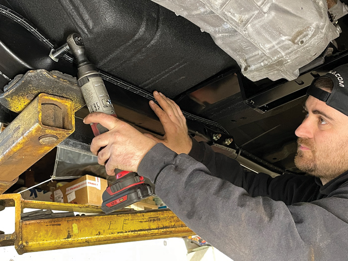
29. With a fresh set of Summit Racing fuel tank mounting straps ready, O’Brien used a transmission jack with a foam pad base to move the tank into place and secured it using a 9⁄16-inch socket.

30. The new tank and straps were a perfect fit, giving the car a fresh OEM-style look.

31. Using the front tank strap as a mounting point, the Summit Racing Universal LS fuel filter/regulator (PN 03-0263) was anchored in place. The kit comes complete with -6AN quick-connect fittings and fuel rail fitting to make the install a snap.


33. After measuring the -6AN Summit Racing braided nylon hose for the fuel supply to the engine, it was cut, lubricated with Aeroquip hose assembly lube, and fittings were installed to the line.

35. To supply the fuel rails, a -6AN Y-block from Redhorse Performance was used, combined with fittings from Russell Performance and Summit Racing -6AN braided nylon hose.

36. A pair of -8AN hex plugs were installed to the front of the fuel rails.

37. Here you can see the Y-block with fuel supply lines to the rear of the fuel rails to complete the installation.
SOURCES