
 Images by The Author
f this were a big pharma ad, right now we’d be telling you about a silent killer of early Chevys and try to scare the pajamas off you. But really, this is a somewhat common malady with older Chevy muscle cars that you may not even know is a problem. Driving around under city lights at night, there’s plenty of illumination on the boulevards and freeways so that dim headlights aren’t a major issue. But take a cruise across the western desert or in the Midwest on a moonless night and you’ll soon discover that anything over 50 mph becomes an issue with outdriving your headlights.
The modern solution has been to upgrade to LED headlights and several companies offer excellent bulbs that project a piercing bright light like a brand-new Lexus. The only problem for guys like us with a four-headlight Chevelle or El Camino is that it will require an investment of over $400 to cover new LED headlights. Thankfully, there’s another solution.
We decided to upgrade our headlights with a simple American Autowire kit that will use a pair of relays to put maximum voltage into the headlights, which will bypass the voltage drop through the headlight switch. The headlight switch then becomes merely the trigger to complete the circuit through the new relays.
The original headlight circuit designed by GM perhaps as far back as the 1950s that continued through multiple decades was to route electrical power from the battery through a bus bar in the horn relay up into the fuse box where it split off into several locations, including the headlight switch. Once the headlights are switched on, the power is forced to travel from the switch through the floor-mounted dimmer and then back through the firewall and finally out to the headlights.
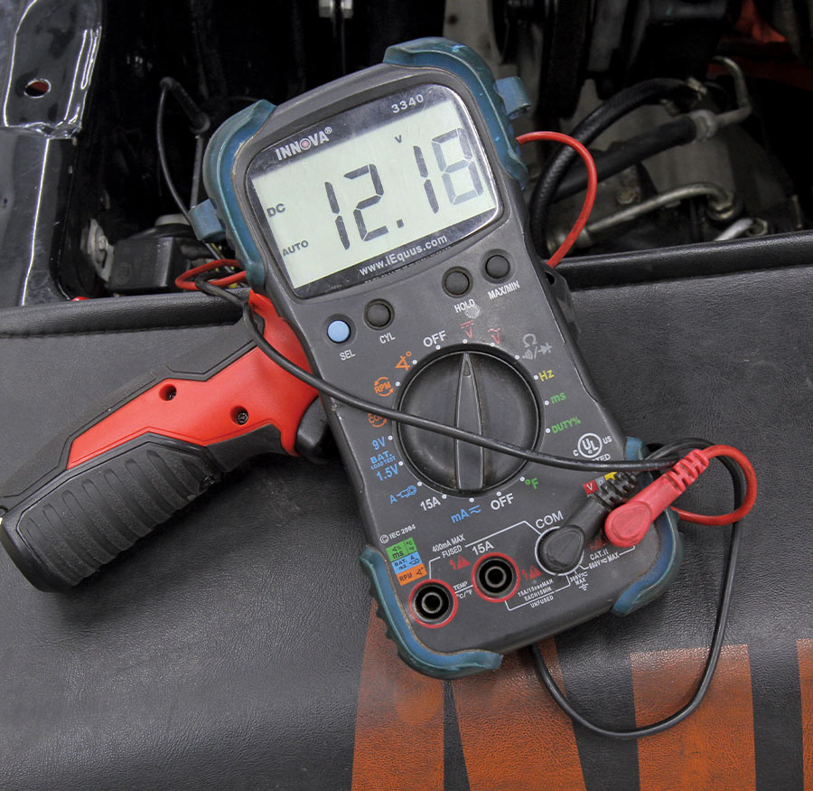
The problem with this rather circuitous route is that it is very inefficient, creating a significant loss of voltage along the way. As a test, we checked voltage at the battery on our 1965 El Camino with a voltage of 12.6 V (engine off). Then we measured the voltage at the driver side outboard headlight and generated a reading of 11.2 V, which means the headlights lost over 10 percent of the voltage following this tortuous path.
We also decided to improve the brightness of the taillights on our El Camino since more than one fellow hot rodder has suggested that our taillights emit about as much light as a pair of tiny birthday cake candles behind our taillight lenses.
In order to create a more efficient path to enlighten our headlights, we need to understand how electrical relays can help this situation. An electrical relay is a simple device that uses a low amperage signal to complete an electrical connection to a higher amperage device. In our case, we will be using the voltage from the headlight switch to trigger the relay. The advantage of this conversion is that the relays will be located very close to the alternator/battery source. By doing this, the lower voltage signal from the headlight switch is only going to be used to trigger the relay, which will then supply nearly 100 percent system voltage to the headlights.
Because the relay pulls power from the bus bar where full system voltage is present, we can eliminate voltage drop through the headlight and dimmer switches and feed full system voltage to the headlights. This will result in much brighter headlights. It’s really a very simple system requiring only a few minor changes to the original headlight circuit.
If you want to get an idea of how much brighter your headlights will be using a set of relays, you could rig up a test wire directly from the battery to the headlights and compare that amount of light intensity to the brightness your headlights are capable of when operated by the original circuit through the headlight switch. This simple test will quickly reveal the benefit of converting to a headlight relay system.
While you could certainly go out and buy a pair of simple Bosch relays and some wire and convert your system, we discovered a complete kit from American Autowire that collects all the components you will need into one part number. The kit comes with a pair of relays for either a two- or four-headlight system as well as the relay connectors and the lengths of wire and additional connectors needed to complete the conversion.
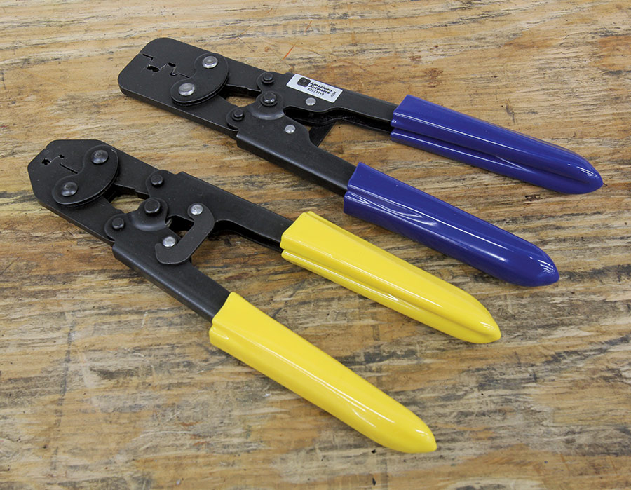
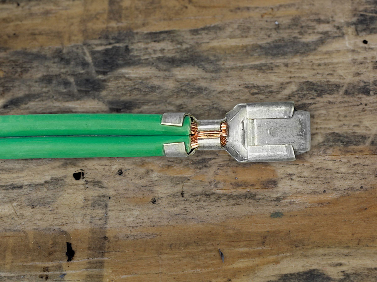
American Autowire also recommended using their single- and double-crimp tools as part of this conversion. The tools are necessary to ensure the proper wiring crimps are made. A better connection ensures that all the voltage supplied by the relays will in fact arrive at the headlights. Plus, the tools produce a professional-style crimp that is not always achievable with budget versions.
The crimping process is important enough that American Autowire has produced an online video explaining exactly how to make the proper crimps for both small wiring connections as well as the double crimps necessary when wiring dual headlights. While the tools are pricey, they are exceptionally well built and will serve you well throughout a lifetime of automotive wiring adventures.
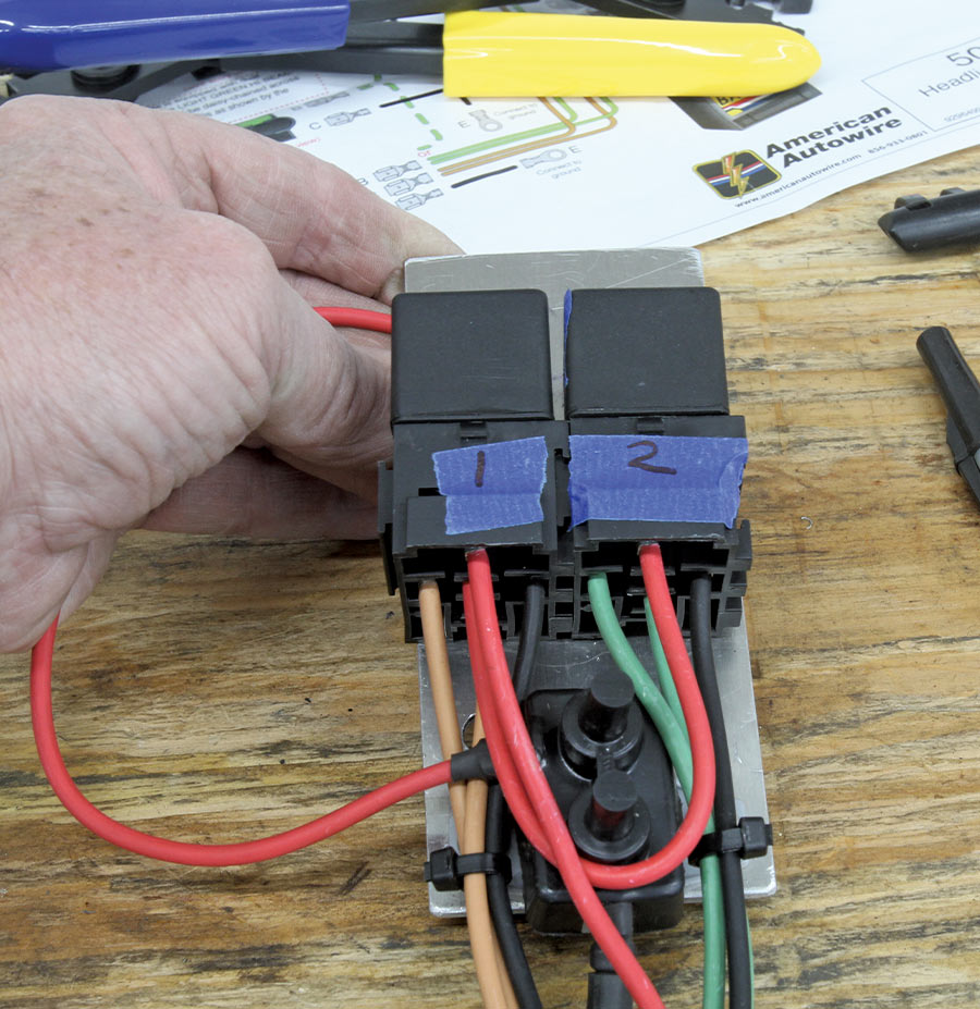
We spent a little extra time building a small aluminum plate to mount the two relays and the circuit breaker that is included in the kit. We attached this mount to the radiator support using existing holes in the support so that we could mount the relays without having to drill more holes. The idea was to minimize the length of the leads from the horn relay to the relays to supply the most amount of voltage to the relays.
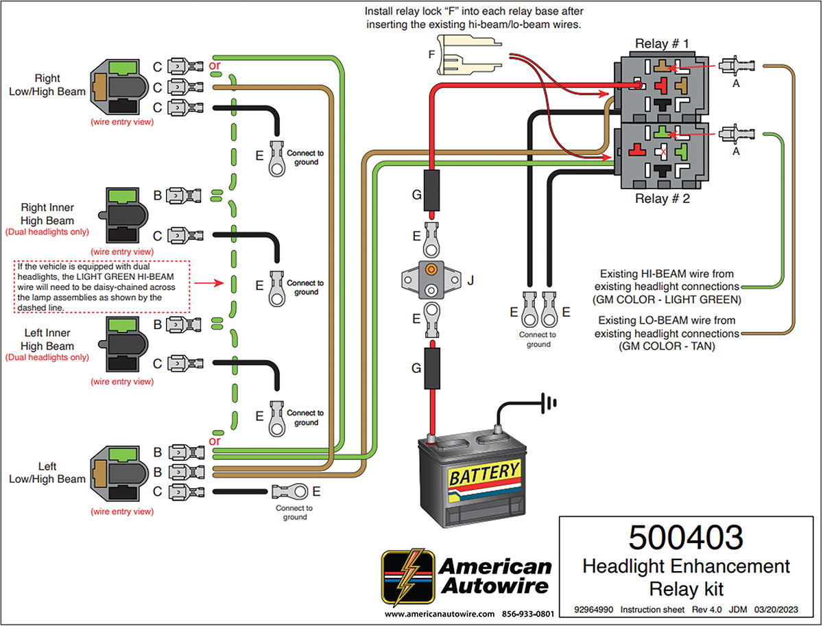
We then followed American Autowire’s color instructions supplied with the kit to wire the relays into the headlight circuit. The existing low-beam wire will be cut off and a new connector will be installed to supply the trigger voltage for the low beams at relay number 1. The same process will be done on the high-beam side for relay number 2. The instruction sheet is very clear on how to go about this, and the kit supplies new headlight and relay connectors so you don’t have to deal with decades-old connectors and wiring.
Once we completed all the wiring connections, we tested the circuit, which at first worked fine. Soon after hitting the dimmer switch several times, the switch failed, which required a trip to the auto parts store for a replacement. With that conversion completed, we then tested the voltage at the headlights again. Previously we had recorded only 11.2 V but with the relays in place, the voltage to the headlights jumped to 12.17 V, a significant 0.97V increase.
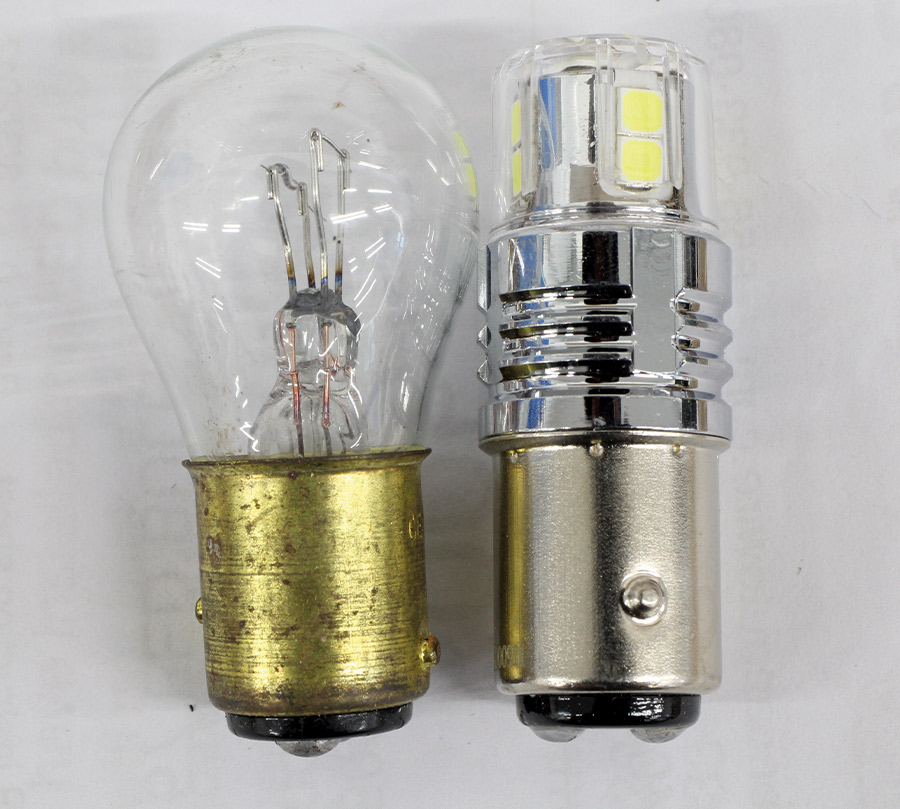
With the headlights rewired, we then moved to the rear of the car where we used a pair of 1157-style LED bulbs to replace the existing incandescent versions. We also exchanged the front parking light bulbs with LED as well so that all four corners were consistent.
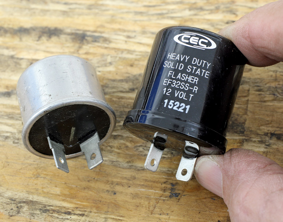
These new LED bulbs require much less energy to create a brighter intensity, but this also means you must replace the original turn signal flasher with a solid-state flasher that is compatible with the LED bulbs. This will allow your turn signal LED bulbs to flash correctly. As a matter of full disclosure, we must also report that the new flasher does not make that familiar clicking sound when the turn signal is working.
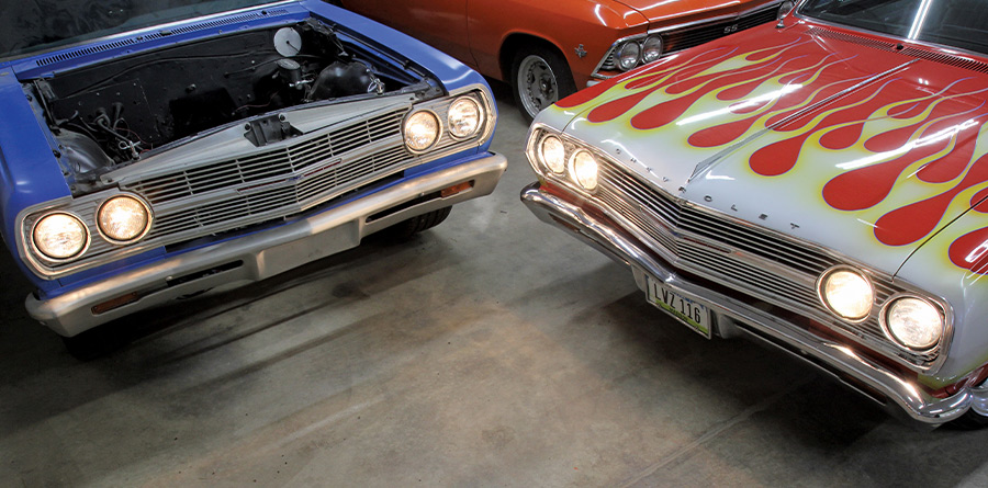
With the headlights and LED turn signal and taillight bulbs converted, we waited for nighttime to evaluate our conversion. It was immediately obvious that our headlights are now much brighter. We live in a very rural setting where deer with suicidal tendencies are prevalent on our country roads. Our brighter headlights now give us a much broader and more distant view of the countryside so we can keep those deer at a safe distance from our El Camino. If nothing else, it makes nighttime cruising a much more enjoyable experience.


 SOURCE